
Double apron drafting unit for spinning frame

A spinning frame and apron technology, applied in the dual fields of the machine, can solve problems such as damage

Inactive Publication Date: 2004-10-13
MASCHINENFABRIK RIETER AG
View PDF3 Cites 0 Cited by
  • Summary
  • Abstract
  • Description
  • Claims
  • Application Information

AI Technical Summary

Problems solved by technology

This measure in fact destroys the boundary layer of the undesired air flow, but the above-mentioned disadvantage still exists here, that is, the pair of aprons must be terminated at a greater distance upstream of the pair of output rollers

Method used


Image

  • Double apron drafting unit for spinning frame
  • Double apron drafting unit for spinning frame
  • Double apron drafting unit for spinning frame

Examples


Embodiment Construction

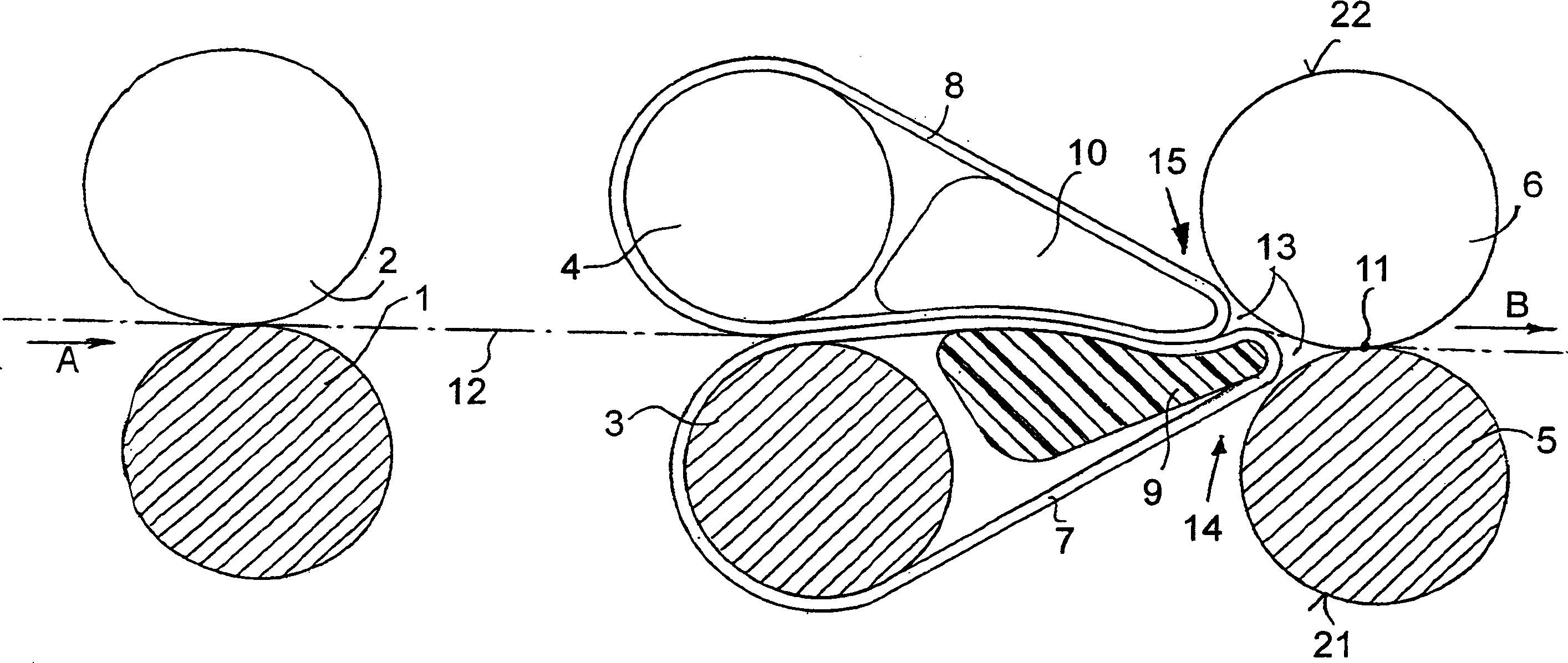
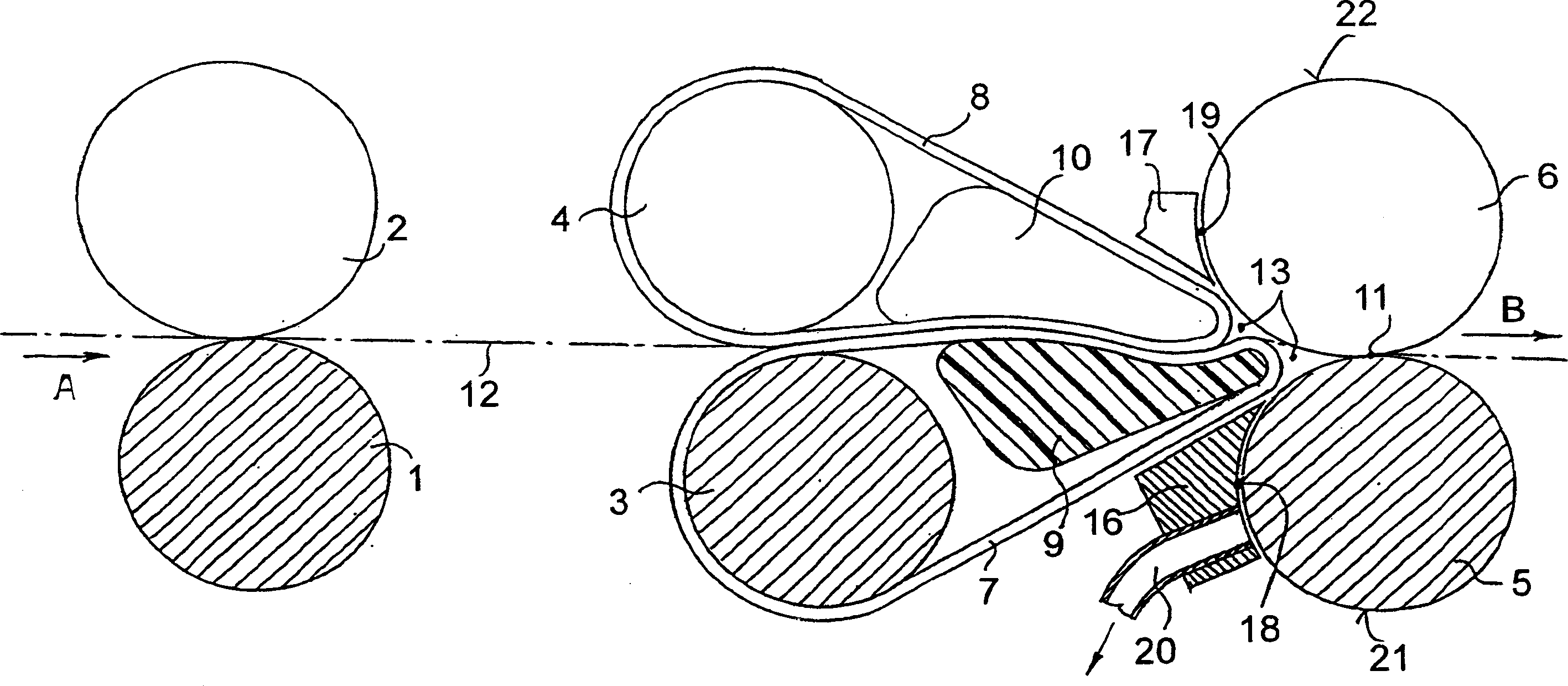
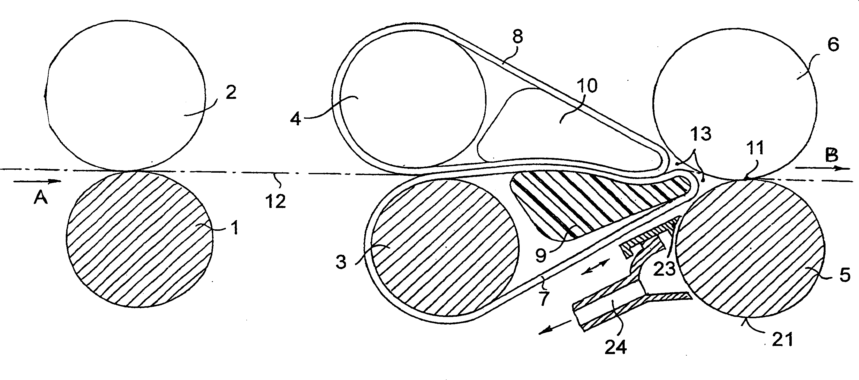
[0025] for spinning machines figure 1 The double apron drafting unit shown uses a three-roller drafting unit and comprises a feed roller 1,2, apron roller pair 3,4 and delivery roller pair 5,6. Rollers 1, 3 and 5 are here driven bottom rollers, rollers 2, 4 and 6 are corresponding pressure rollers on which they are elastically arranged. Apron roller pair 3,4 is surrounded by apron pair 7,8, while apron 7 is the lower apron and apron 8 is the upper apron. Reference numeral 9 designates a guide for the lower apron 7 and reference numeral 10 designates a guide for the upper apron 8 .

[0026] The delivery roller pair 5 , 6 defines a delivery gripping line 11 , at which the drafting of the fiber bundle 12 to be drawn, indicated by a dotted line, ends. The fiber bundle 12 is fed in the feed direction A to the double-apron drafting unit and then in the output direction B downstream of the output gripping line 11 to a twisting device (not shown).

[0027] An advantageous effect on...


PUM

PropertyMeasurementUnit
heightaaaaaaaaaa

Abstract

A double-apron drafting unit for spinning machines has a delivery roller pair and an apron pair arranged upstream therefrom. The apron pair guides a fiber strand in the area of a delivery nipping line, with which it forms a wedge-shaped gap. Devices are provided for keeping air currents, which circulate with the delivery roller pair, away from the area of the delivery nipping line, which devices are located outside of the wedge-shaped gap point formed by the delivery nipping line and the apron pair. The devices are, however, located in direct proximity to the delivery roller pair and the apron pair.

Description

technical field [0001] The invention relates to a double-apron drafting unit for spinning frames, comprising a pair of output rollers with an output gripping wire, and a pair of aprons arranged upstream of the pair of output rollers, the pair of aprons on the The fiber bundle is guided in the region of the output holding line and forms a wedge-shaped gap together with said pair of output rollers, and means are provided for keeping the air flow circulating with the pair of output rollers away from the output holding line. Background technique [0002] In the case of such a double-apron drafting unit, in particular when such a double-apron drafting unit is used in a so-called open-end spinning machine, output speeds can be achieved so that the air flow caused by the rotating output rollers cannot be ignored . Because of the high speed of rotation of the rotating output roller, the rotating roller restricts the air circulating with the roller. The air flow is interrupted at t...

Claims


Application Information

Patent Timeline
Patent Type & Authority Applications(China)
IPC IPC(8): D01H5/88D01H5/00D01H5/26D01H5/86
CPCD01H5/26D01H5/00
Inventor G·施塔莱克N·肖赫
Owner MASCHINENFABRIK RIETER AG
Learn More