
Detection device and detection method for measuring loss degree of aggregate to contact part

A technology for contacting parts and detection devices, applied in measuring devices, material weighing, analyzing materials, etc., can solve problems such as equipment wear, economic loss and waste of equipment and equipment, and save resources, increase production capacity, and infer operating life. Effect

Inactive Publication Date: 2016-08-31
FUJIAN SOUTHERN HIGHWAY MECHANICAL
View PDF5 Cites 1 Cited by
  • Summary
  • Abstract
  • Description
  • Claims
  • Application Information

AI Technical Summary

Problems solved by technology

[0002] Existing pavement machinery, such as drums, mixers, crushers and other equipment, all have contact parts that rub and collide with aggregates during work. Surface machinery manufacturers usually use conventional steel to make contact parts. Before the equipment leaves the factory, it is impossible to get a more accurate estimate of the friction and impact loss between the steel and the aggregate, so it is impossible to select the steel that matches the aggregate according to the service life of the contact parts of the equipment
[0003] Most of the existing easy-to-wear contact parts need to be replaced regularly. The above problems lead to the following problems in the use of the equipment after leaving the factory: First, the steel used in the contact parts has not reached the level of wear and replacement and is replaced in advance to cause waste; Second, the failure to replace the contact parts in time leads to more serious wear and tear on the equipment, which brings economic losses to the equipment manufacturer and the customer who purchases the equipment

Method used


Image

  • Detection device and detection method for measuring loss degree of aggregate to contact part
  • Detection device and detection method for measuring loss degree of aggregate to contact part
  • Detection device and detection method for measuring loss degree of aggregate to contact part

Examples


Embodiment Construction

[0024] The present invention will be further described below through specific embodiments.

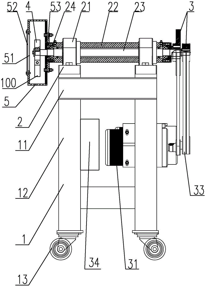
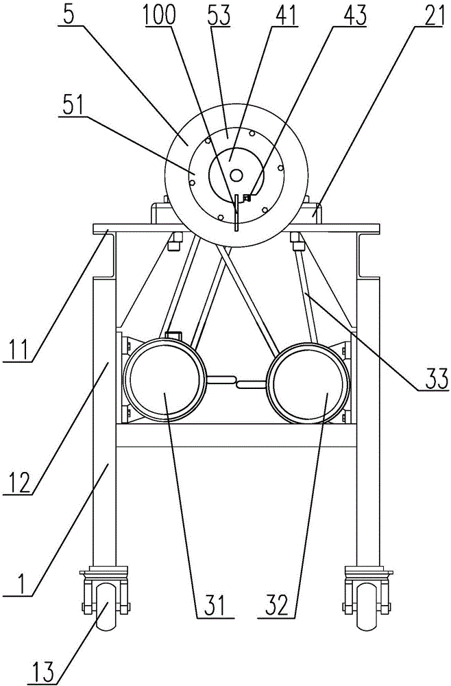
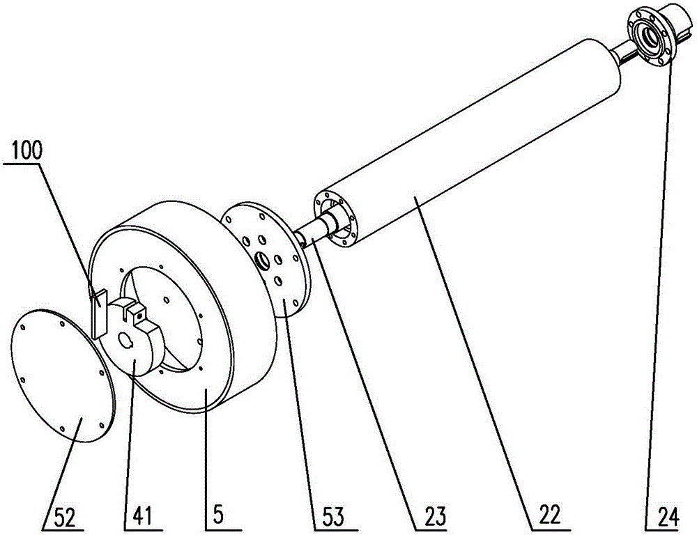
[0025] refer to Figure 1 to Figure 3 As shown, the detection device used to determine the degree of loss of aggregate to contact parts includes a bracket 1, a rotating mechanism 2, a driving mechanism 3, a clamping mechanism 4 and a lifting cylinder 5;

[0026] The support 1 includes an operating platform 11, legs 12 and rollers 13 arranged at the bottom of the legs;

[0027] The rotating mechanism 2 is arranged on the operating platform 11 of the bracket 1, and includes a pair of bearing seats 21, a sleeve 22, a rotating shaft 23, and a bearing assembly 24. The bearing seat 21 is arranged on the operating platform 11, and the sleeve 22 is assembled in the bearing seat 21. , the rotating shaft 23 is installed in the sleeve 22, the bearing assembly 24 is arranged between the sleeve 22 and the rotating shaft 23, one end of the sleeve 22 is connected with the lifting cylinder 5, and the...


PUM


Abstract

The invention relates to the field of construction machinery manufacturing and specifically relates to a detection device and a detection method for measuring loss degree of an aggregate to a contact part. The detection device for measuring the loss degree of the aggregate to the contact part comprises a bracket, a rotating mechanism, a driving mechanism, a clamping mechanism and a raise dust barrel, wherein the rotating mechanism is arranged on the bracket; the rotating mechanism is connected with the rotating mechanism, so as to drive the rotating mechanism to rotate; the rotating mechanism is respectively connected with the clamping mechanism and the raise dust barrel and is used for driving the clamping mechanism and the raise dust barrel to rotate; the clamping mechanism is arranged in the raise dust barrel and is used for mounting a to-be-detected workpiece. The detection device and the detection method can be used for simulating the abrasion degree of the interior of the equipment after long-term rubbing and impacting with the aggregate, more accurately estimating the service life of the contact part, selecting the material for manufacturing contact part according to the practical production requirement, saving a large amount of resources, increasing the yield and achieving the purpose of deducing the service life of equipment.

Description

technical field [0001] The invention relates to the field of construction machinery manufacturing, in particular to a detection device and a detection method for measuring the loss degree of aggregates to contact parts during road surface machinery manufacturing. Background technique [0002] Existing pavement machinery, such as drums, mixers, crushers and other equipment, all have contact parts that rub and collide with aggregates during work. Surface machinery manufacturers usually use conventional steel to make contact parts. Before the equipment leaves the factory, it is impossible to obtain a more accurate estimate of the friction and impact loss between the steel and the aggregate, so it is impossible to select the steel that matches the aggregate according to the service life of the contact parts of the equipment. [0003] Most of the existing easy-to-wear contact parts need to be replaced regularly. The above problems lead to the following problems in the use of the ...

Claims


Application Information

Patent Timeline
Patent Type & Authority Applications(China)
IPC IPC(8): G01N3/56G01N5/00
CPCG01N3/56G01N5/00
Inventor 林伟端黄骁民王惠风田义黄文景严子利
Owner FUJIAN SOUTHERN HIGHWAY MECHANICAL
Learn More