A heat loss test method for a thermal comprehensive test device

A technology of comprehensive testing and testing methods, applied in the testing of machines/structural components, measuring devices, instruments, etc., can solve the problems of difficult measurement, poor accuracy, and low accuracy, and achieve strong operability and accuracy High, precise results

Active Publication Date: 2017-03-08
NUCLEAR POWER INSTITUTE OF CHINA
View PDF6 Cites 0 Cited by
  • Summary
  • Abstract
  • Description
  • Claims
  • Application Information

AI Technical Summary

Problems solved by technology

[0005] The technical problem to be solved by the present invention is that the heat loss test method of the traditional thermal comprehensive test device is to measure the fluid flow rate and inlet and outlet temperature of each equipment one by one, then calculate the thermal power absorbed by the fluid in each equipment and find out the thermal power of all equipment. The total heat loss of the test device can be obtained by subtracting the total heat power from the power of the heat source. This test method is difficult to measure the temperature difference at low power levels and the flow rate at low flow rates, and the accuracy is poor. There is a certain error in the accumulation of heat loss power , low reliability, unable to meet the higher requirements of the thermal comprehensive test, the purpose of the present invention is to provide a heat loss testing method of the thermal comprehensive test device, including establishing the heat loss test conditions, blocking the cold source, controlling the power of the heat source , determining heat balance and other steps, the whole operation step does not depend on the flow rate, the accuracy of temperature measurement is not high, and no complicated data processing is required to obtain high-precision and reliable heat loss power, which solves the problem of thermal comprehensive test simulation Technical problems such as low level, low temperature measurement and low flow measurement difficulty and low accuracy

Method used


Image

  • A heat loss test method for a thermal comprehensive test device

Examples


Embodiment 1

[0052] A heat loss test method of a thermal comprehensive test device of the present invention comprises the following steps,

[0053] a. Determine the heat loss test conditions

[0054] Determine the pressure and temperature of the reactor and the primary circuit system, the waste heat removal system, and the temperature of the pressurizer 4, that is, determine a working point, including the reactor and the primary circuit system, and the pressure of the waste heat discharge system is 15MPa, and the reactor and the primary circuit The temperature of the system is 300°C, and the temperature of the regulator 4 is 350°C.

[0055] b. Establish heat loss test conditions

[0056] b.1. According to the heat loss test conditions determined in step a, lay insulation cotton in the reactor, the primary loop system, and the secondary loop system, start the main pump 6 and the waste heat discharge pump 11, and put the main heat source simulator 1 into the reactor for simulation The devi...

Embodiment 2

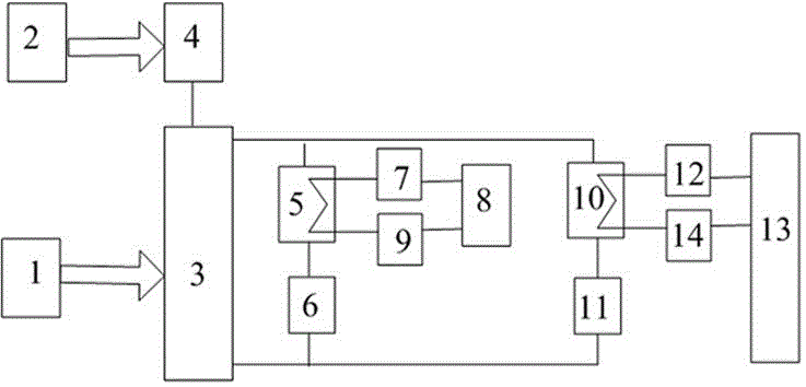
[0066] Such as figure 1 As shown, the thermal comprehensive test device includes a reactor and a primary circuit system, a secondary circuit system, a waste heat removal system, and a cold source simulation system. The reactor and a primary circuit system include a main heat source simulator 1 and a secondary heat source simulator 2 , reactor simulator 3, pressurizer 4, steam generator simulation body 5, main pump 6, the main heat source simulator 1 is connected with reactor simulator 3, main pump 6, steam generator simulation body 5 in sequence, and the secondary heat source The simulator 2 is connected with the reactor simulator 3 and the steam generator simulation body 5 sequentially through the voltage stabilizer 4 .

[0067] Among them, the reactor and the primary loop system are also called the main system of the primary loop of the reaction. The function of the voltage stabilizer 4 in this system is to control the pressure of the coolant and prevent the core from deviat...

Embodiment 3

[0082] The present embodiment is as the comparative example of embodiment 1 and 2:

[0083] The heat loss test method of the existing thermal comprehensive test device will be described, including the following steps:

[0084] a. Determine the heat loss test conditions

[0085] Same operation as step a in Example 1.

[0086] b. Establish heat loss test conditions

[0087] The operation is the same as step b in Example 1.

[0088] c. Measure flow and temperature parameters

[0089] Keep the power of main heat source simulator 1 and secondary heat source simulator 2 constant, and stabilize the loop parameters for 20 minutes; measure the flow rate of main pump 6 and waste heat discharge pump 11, and measure reactor simulator 3, steam generator simulation body 5, and main pump 6. Equipment such as steam turbine simulator 8, waste heat discharge cooler 10, waste heat discharge pump 11, cold source simulator 13, and the inlet and outlet temperatures of pipelines between each devic...


PUM


Abstract

The invention discloses a heat loss testing method of a thermal comprehensive test device, comprising the following steps: a. determining the heat loss test working condition, b. establishing the heat loss testing working condition, c. blocking the secondary circuit system and the waste heat discharge system 1. The cold source of the cold source simulation system, d, carry out the heat loss test, e, judge the heat balance state, the heat loss test method of the present invention is simple and reliable, and the heat loss power of the thermal engineering comprehensive test device is the main heat source under the heat balance state The sum of the heat source power of the simulator and the secondary heat source simulator, the heat loss test method of the present invention does not rely on the accuracy of low flow rate flow measurement, does not require high temperature measurement accuracy, does not require complex data processing, and has no cumulative error. The heat loss test power with high accuracy and reliability can be obtained.

Description

technical field [0001] The invention relates to the technical field of heat loss testing, in particular to a heat loss testing method of a thermal comprehensive test device. Background technique [0002] In the field of nuclear power technology, the thermal comprehensive test device must accurately simulate the nuclear reactor system and the prototype of the ad hoc safety system. The thermal boundary simulation is one of the core issues of the overall simulation. If the thermal boundary simulation is too distorted, even if the heat source is well obtained However, if the simulation is performed, the cooling capacity of the ad hoc safety system still has a large distortion, which means that the test results cannot be fed back to the prototype, and the effectiveness of the thermal comprehensive test cannot be guaranteed. Therefore, the thermal boundary must be accurately simulated, and the basis of thermal boundary simulation is to accurately obtain the heat loss power of the ...

Claims


Application Information

Patent Timeline
Patent Type & Authority Patents(China)
IPC IPC(8): G01M99/00
CPCG01M99/002
Inventor 徐建军周慧辉黄彦平谭曙时朱海雁
Owner NUCLEAR POWER INSTITUTE OF CHINA
Why Eureka
Try Eureka