Zero Error Test of Angle Measuring System and Comprehensive Error Compensation Method

A technology of zero error and comprehensive error, which is applied in the field of angle measurement error testing and calibration, can solve the problems of insufficient zero error testing and deduction, significant compensation effect, and discounted compensation effect, so as to achieve good overall compensation effect and strong engineering The effect of applying value

Active Publication Date: 2018-08-03
TSINGHUA UNIV
View PDF4 Cites 0 Cited by
  • Summary
  • Abstract
  • Description
  • Claims
  • Application Information

AI Technical Summary

Problems solved by technology

However, the data measured by the multi-faceted prism test method is sparse, and it is generally only used to grasp the error profile. There are few reports on using the test data for error compensation. and the deduction is insufficient, the compensation effect is significant only at the sampling point of the error sample, and the compensation effect is greatly reduced at other positions

Method used


Image

  • Zero Error Test of Angle Measuring System and Comprehensive Error Compensation Method
  • Zero Error Test of Angle Measuring System and Comprehensive Error Compensation Method
  • Zero Error Test of Angle Measuring System and Comprehensive Error Compensation Method

Examples


specific Embodiment 1

[0068] Specific embodiment 1 based on the polyhedral prism inductosynchronous angle measurement system zero error and subdivision error test (assuming that the number of pole pairs m of the precision measuring element is 360)

[0069] 1) Test system preparation.

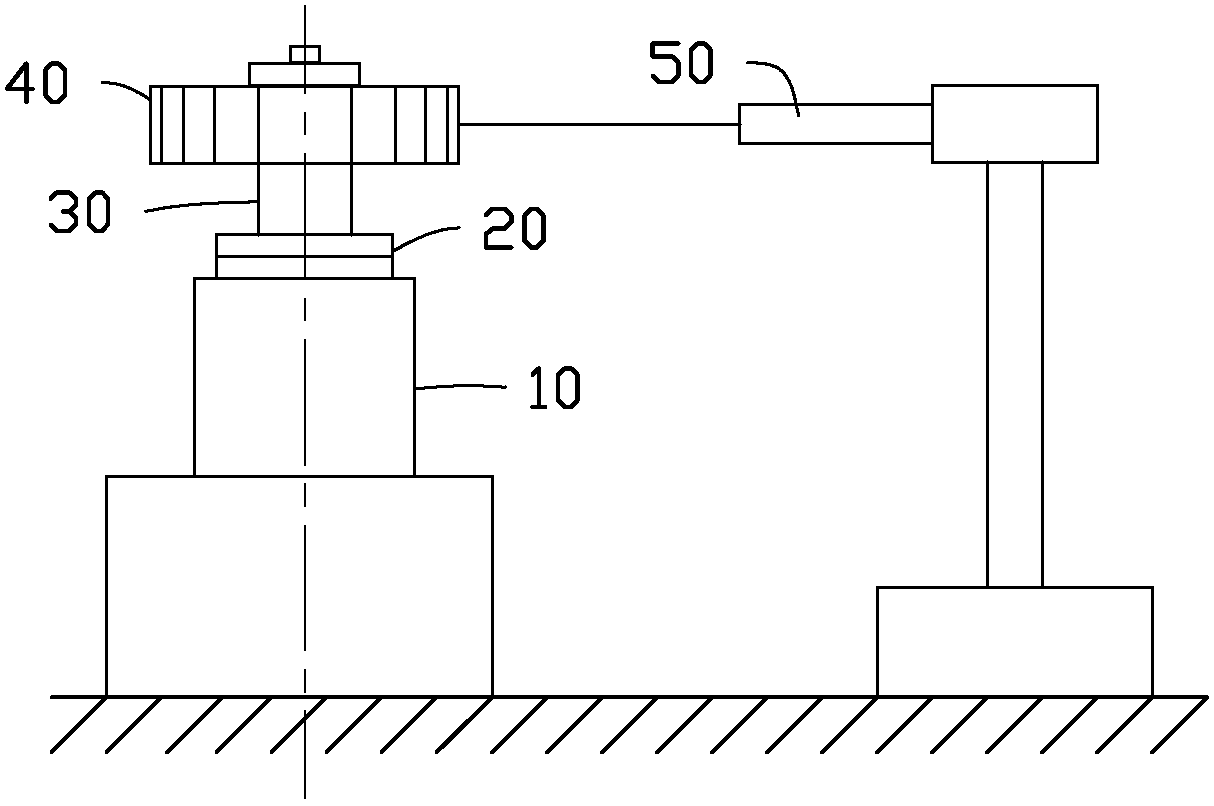
[0070] cling to figure 1 As shown, the polygonal prism is installed on the shaft end of the measured shaft through tooling, and the autocollimator and the measured shaft are placed on the same base. Adjust the optical axis of the autocollimator to be at the same height as the axis of the prism, rotate the measured axis, and adjust the tower difference to the allowable range (≤100″).

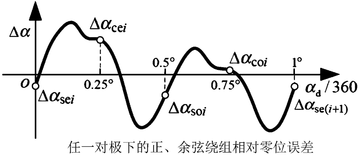
[0071] 2) Test and calculate the relative zero error of 4 sets of 1° intervals.

[0072] a) Using a 72-sided prism to test the relative zero position error of 4 sets of 5° intervals. Start the test with the 0° output of the angle measurement system as the starting point. At this time, the reading of the autocollimator is cleared, and...

Embodiment 2

[0075] Embodiment 2 Error compensation based on the zero position error and subdivision error test of the inductive synchronizer angle measurement system based on the polyhedral prism

[0076] 1) Zero error calculation and compensation. After the odd and even zero position errors of any pair of poles are calculated by formula 1, the error compensation amount Δα caused by the zero position error in different intervals of any pair of poles is calculated as shown in Table 1 z , and directly subtract it from the current sampling angle of the angle measurement system, and record the angle output after deducting the zero error as θ1. Assuming that the current sampling angle of the goniometric system is 234.8710°, the calculation sequence number i in Table 1=234.

[0077] Table 1 Calculation error compensation amount Δα z

[0078]

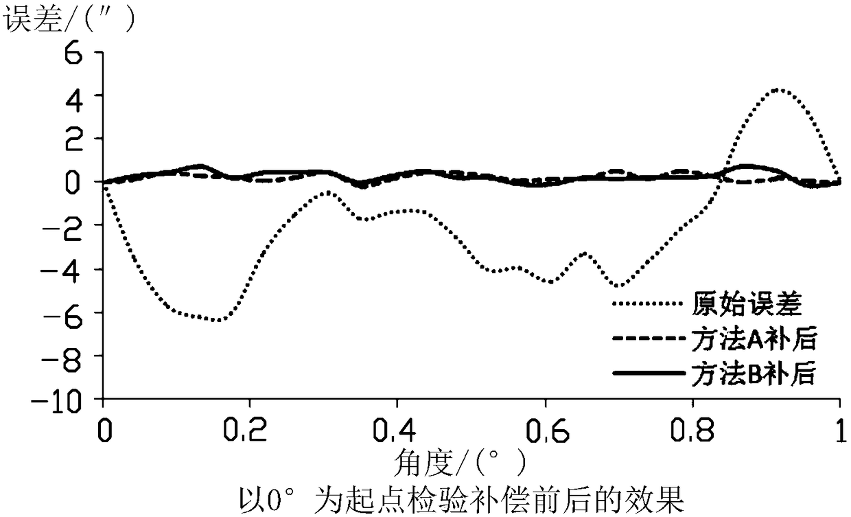
[0079] 2) Subdivision error calculation and compensation. After compensating the influence of the zero position error as shown in step 1), take th...


PUM


Abstract

The invention discloses error test and compensation methods of an induction synchronizer angle measurement system utilizing a polygon. By adopting the methods provided by the invention to carry out error testing and compensation, a relatively good global compensation effect is obtained, and the problem of other testing and compensation methods utilizing the polygon that the compensation effect is only realized at error sampling points and is unavailable at non-sampling points is solved. By adopting the polygon mode, the error testing and compensation of the induction synchronizer angle measurement system are realized, and compared with a high precision raster mode, the methods provided by the invention is wider in engineering applicability.

Description

technical field [0001] The invention relates to the technical field of angle measurement error testing and calibration, in particular to a zero position error test and comprehensive error compensation method of an angle measurement system. Background technique [0002] The angle measurement system composed of inductive synchros has high measurement accuracy and good anti-interference performance, and is widely used in precision angular position servo systems. The comprehensive error data of the inductosynchronous angle measurement system is divided into zero position error and subdivision error. The comprehensive error characteristics of the inductive synchronizer angle measurement system are stable, and software compensation is an effective means to improve the system accuracy. [0003] Different methods such as linear interpolation, model fitting, neural network or wavelet analysis can be used for software compensation of the angle measurement system error of the inductiv...

Claims


Application Information

Patent Timeline
Patent Type & Authority Patents(China)
IPC IPC(8): G01B7/30
CPCG01B7/30
Inventor 李海霞张嵘韩丰田贺晓霞
Owner TSINGHUA UNIV
Why Eureka
Try Eureka