
Clamping device

A gripper and gripper technology, which is applied in the field of gripping devices, can solve the problems of falling objects to be gripped, inconvenient disassembly and assembly, affecting gripping efficiency, etc., and achieves convenient disassembly, assembly and maintenance, improved service life, and increased friction. force effect

Inactive Publication Date: 2016-08-31
浙江博雷重型机床制造有限公司
View PDF5 Cites 9 Cited by
  • Summary
  • Abstract
  • Description
  • Claims
  • Application Information

AI Technical Summary

Problems solved by technology

[0002] With the popularization of industrial automation, more and more factories have introduced automated production lines. In these lines, in order to make parts or semi-finished products can be smoothly transferred between various processes, parts or semi-finished products are generally realized by clamping devices. At present, the transfer of semi-finished products usually adopts the clamping device with complex structure, inconvenient disassembly and bulky volume, and the friction force between the clamping device and parts or semi-finished products will decrease during long-term use, which will easily cause the clamped object to fall , affecting the gripping efficiency. In addition, due to the uncertain size and shape of the gripped object, it is not easy to control the opening and closing range of the gripping device. Especially after the gripped object falls, the two jaws are easy to collide and deform. Therefore, there is an urgent need for a Grippers that meet your needs

Method used


Image

  • Clamping device
  • Clamping device
  • Clamping device

Examples


Embodiment Construction

[0026] Embodiments of the present invention are described in detail below, examples of which are shown in the drawings, wherein the same or similar reference numerals designate the same or similar elements or elements having the same or similar functions throughout. The embodiments described below by referring to the figures are exemplary and are intended to explain the present invention and should not be construed as limiting the present invention.

[0027] In describing the present invention, it should be understood that the terms "center", "longitudinal", "transverse", "length", "width", "thickness", "upper", "lower", "front", " The orientations or positional relationships indicated by "rear", "left", "right", "vertical", "horizontal", "top", "bottom", "inner", "clockwise", "counterclockwise" are based on the attached The orientation or positional relationship shown in the figure is only for the convenience of describing the present invention and simplifying the description...


PUM


Abstract

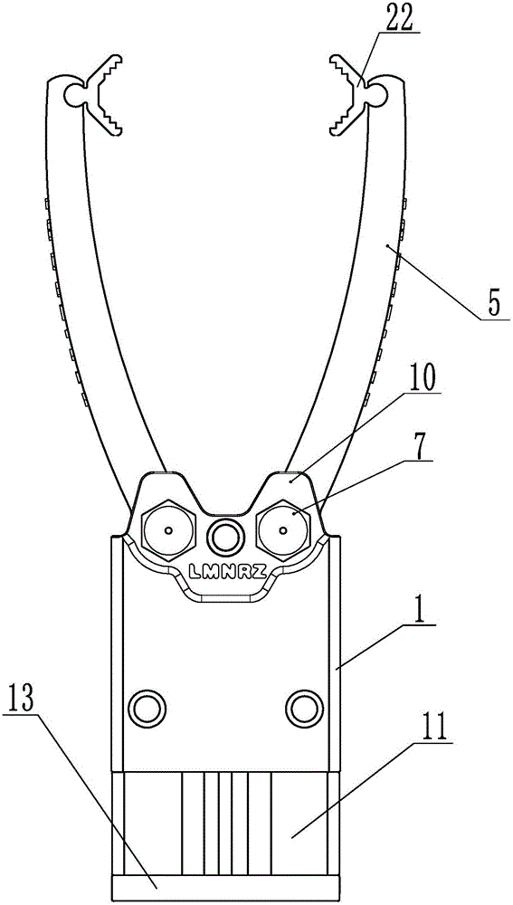
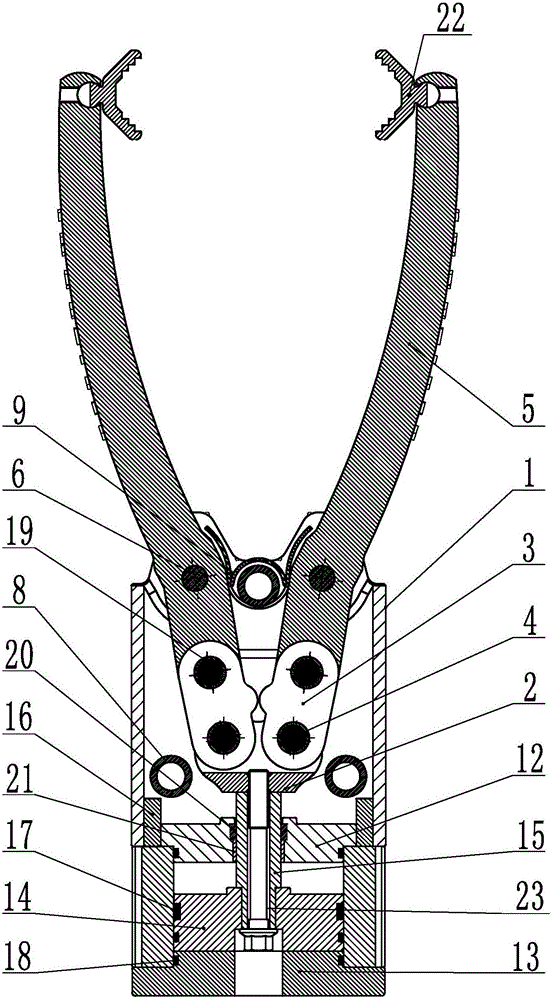
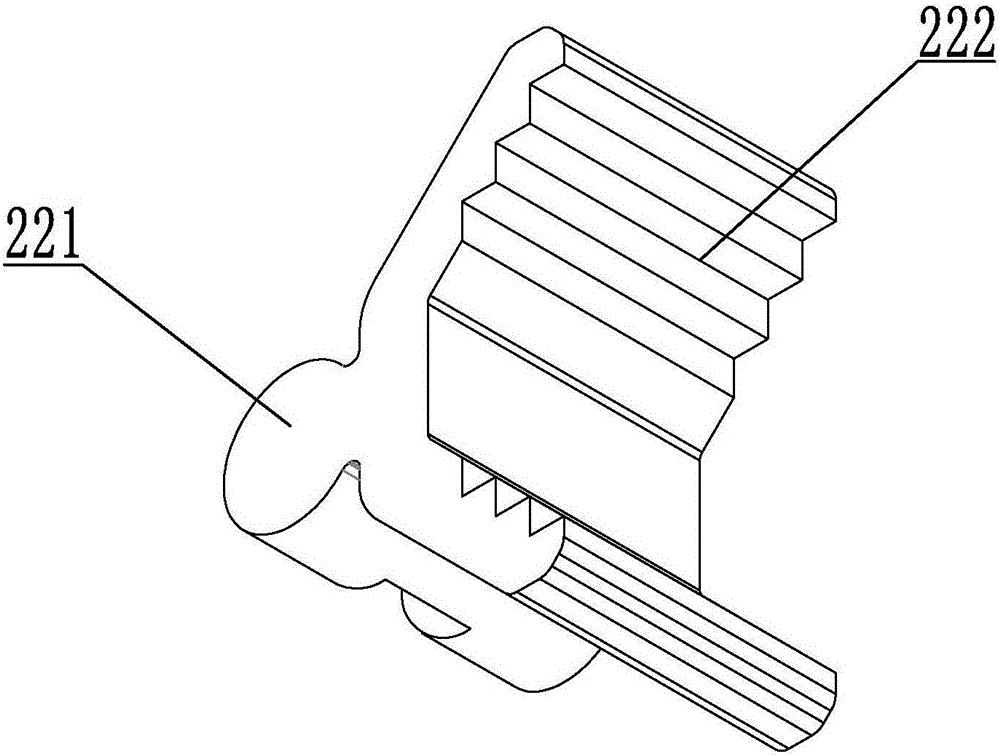
The invention relates to a clamping device. The clamping device comprises clamping jaws, a jaw cavity body, clamping jaw mounting plates, connecting rods, a push block and an air cylinder; a piston rod of the air cylinder is fixed to the lower end of the push block, the left end and the right end of the push block are hinged to the two connecting rods through connecting rod pins, and the other ends of the two connecting rods are hinged to the two clamping jaws correspondingly; the jaw cavity body is fixed to the upper end of the air cylinder, the two clamping jaw mounting plates are fixed to the upper portions of the front inner wall and the rear inner wall of the jaw cavity body, and extend out of the upper end of the jaw cavity body, and the lower middle portions of the two clamping jaws are hinged between the two clamping jaw mounting plates at an interval through clamping jaw pins; spring pieces are fixed between the two clamping jaws through mounting pins; and according to the clamping device, a chuck is easy to replace, use is convenient, and the service life of the clamping device is prolonged. The piston rod and a piston of the air cylinder and the push block are fixedly dismounted and mounted through a bolt, maintaining is convenient, the piston of the air cylinder is in an oval shape, and the thickness of the whole clamping device is reduced.

Description

technical field [0001] The invention relates to a gripping device. Background technique [0002] With the popularization of industrial automation, more and more factories have introduced automated production lines. In these lines, in order to make parts or semi-finished products can be smoothly transferred between various processes, parts or semi-finished products are generally realized by clamping devices. At present, the transfer of semi-finished products usually adopts the clamping device with complex structure, inconvenient disassembly and bulky volume, and the friction force between the clamping device and parts or semi-finished products will decrease during long-term use, which will easily cause the clamped object to fall , affecting the gripping efficiency. In addition, due to the uncertain size and shape of the gripped object, it is not easy to control the opening and closing range of the gripping device. Especially after the gripped object falls, the two jaws are ea...

Claims


Application Information

Patent Timeline
Patent Type & Authority Applications(China)
IPC IPC(8): B65G47/90B25J15/08
CPCB65G47/901B25J15/08B65G2201/02
Inventor 高尔荣裘小龙
Owner 浙江博雷重型机床制造有限公司
Learn More