Suspension type filter

A kind of filter and suspension technology, which is applied in the direction of membrane filter, filter separation, mobile filter element filter, etc., can solve the problems of heavy filter work load, rust, and reduced work efficiency, so as to avoid work failure and improve Durability and low running cost

Inactive Publication Date: 2016-08-31
XINJIANG HUILI IRRIGATION TECH CORP
View PDF4 Cites 1 Cited by
  • Summary
  • Abstract
  • Description
  • Claims
  • Application Information

AI Technical Summary

Problems solved by technology

[0003] At present, widely used filters, such as Chinese patents CN202270401U and CN201565186U, are all self-cleaning filters. Although the self-cleaning of the filter screen can be realized, the actual use has the following problems: 1. It must be fixed on a fixed 2. The working state needs to use the water pump to realize the water inlet and outlet of the filter; 3. There are special requirements for the filtered water source, for example, the water in the filtered water channel cannot work for a long time, mainly the working water pump and the filter screen The cleaning does not meet the actual requirements
[0005] 1. The filter cartridge is driven by a motor. In actual use, the rack will shake in the water, causing the motor to fail to drive the filter cartridge to rotate normally, reducing work efficiency;
[0006] 2. Larger impurities in the channel, such as branches, dirt, etc., will be stuck on the float, which will increase the difficulty of manual cleaning, and will also cause the entire filter to be overloaded;
[0007] 3. Since the filter cartridge is soaked in water for a long time, the transmission problem between the motor and the filter cartridge cannot be solved well. After working for a long time, there will be slipping or rusting.

Method used


Image

  • Suspension type filter
  • Suspension type filter
  • Suspension type filter

Examples


Embodiment 1

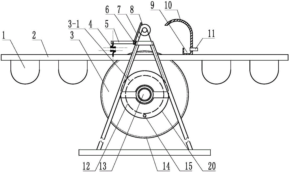
[0043] Embodiment 1: refer to figure 1, is a structural schematic diagram of Embodiment 1 of the present invention, comprising a fixed frame (2), characterized in that: the fixed frame (2) is at least provided with a drive mechanism (8) and a filtering device, and the filtering device includes a filter screen B (14 ) and at least two end plates, the filter screen B (14) forms a cylindrical cylinder, the end plates are located at both ends of the cylindrical cylinder, and the end plate and the filter screen B (14) form a filter cavity, at least An end plate is provided with a water outlet (13), so that the water to be filtered enters the filter cavity through the filter screen B (14) from the outside, and then is discharged from the water outlet (13); the end plate is provided with a central axis, and the filter screen B (14) and the filter cavity formed by the end plate are fixed on the fixed frame (2) by the central axis, and can rotate around the central axis, and the above-...

Embodiment 2

[0045] Embodiment 2: Compared with Embodiment 1, the difference of this embodiment is that: the fixed frame (2) is also provided with a water collection tank (10), and the water collection tank (10) is located at the rear of the filter device, collecting The top of the water tank (10) is arc-shaped, and the bottom is provided with an inverted "Π"-shaped miscellaneous tank (9). ) to discharge impurities in the direction of water flow.

[0046] In actual use: in the flowing water, there will be impurities close to the frame. By setting the water collection tank (10), not only the water intake of the filter device can be increased, but also the impurities in the water can be collected in the miscellaneous collection tank at the lower part of the water collection tank (10) (9), finally discharged by the miscellaneous discharge port (11), which does not affect the work of the whole system and prevents impurities in the water from winding on the float (1) or the fixed frame (2).

Embodiment 3

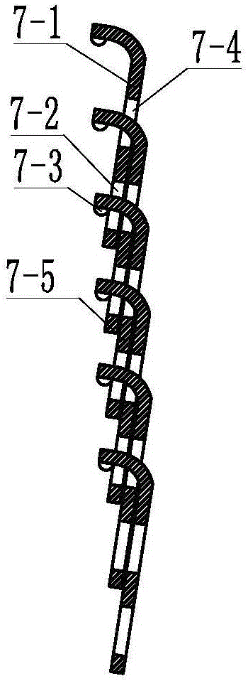
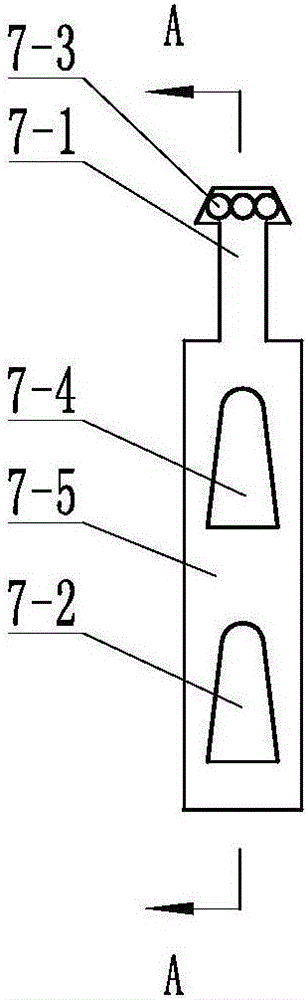
[0047] Embodiment 3: refer to Figure 2-5 , is a structural schematic diagram of Embodiment 3 of the present invention. Compared with any embodiment of Embodiments 1 to 2, the difference of this embodiment is that the driving mechanism (8) and the filter device are driven by a transmission chain (7), The transmission chain (7) is composed of a plurality of monomers which are plugged end to end, and the monomers include a chuck (7-1) and a body (7-5), and the body (7-5) is provided with a fixing hole A ( 7-2) and fixing hole B (7-4), the above chuck (7-1) can pass through fixing hole A (7-2) and / or fixing hole B (7-4), and with fixing hole A (7-2) and / or fixing hole B engage with each other.

[0048] In actual use: pass the chuck (7-1) through the fixing hole A (7-2) or the fixing hole B (7-4), and connect at the end to form a strip-like chain.

[0049] Or, pass the chuck through the close fixing hole B (7-4), and then pass through the second fixing hole A (7-2), and so on, t...


PUM


Abstract

The invention discloses a suspension type filter. The suspension type filter comprises a fixing frame (2), wherein a float (1) is arranged on the fixing frame (2). The suspension type filter is characterized in that at least a driving mechanism (8), a water collecting tank (10) and a filtering device are arranged on the fixing frame (2); the driving mechanism (8) is arranged on a bracket (5) which is hinged to the fixing frame (2); a balance spring (4) is arranged between the bracket (5) and the fixing frame (2); the driving mechanism (8) and the filtering device are in transmission by a transmission chain (7); the water collecting tank (10) is arranged behind the filtering device, the upper part of the water collecting tank (10) is in an arc shape, and the lower part of the water collecting tank (10) is provided with an inverted n-shaped impurity collecting tank (9); the impurity collecting tank (9) is provided with an impurity discharge opening (11), and the impurity discharge opening (11) is used for discharging impurities to the water flow direction.

Description

technical field [0001] The invention belongs to the field of agricultural irrigation and relates to a filter, in particular to a suspension filter. Background technique [0002] Water resources are very precious, and water saving has become the trend of sustainable development of industry and agriculture. In our country, water resources are very scarce, and the per capita water resource share is only a quarter of the world's average level, and agriculture is a large water user. Therefore, it is imperative to accelerate the development of agricultural water conservation, and the rapid development of micro-irrigation technology requires Advanced filtering equipment is compatible with it. Among them, filtering equipment is very important equipment. [0003] At present, widely used filters, such as Chinese patents CN202270401U and CN201565186U, are all self-cleaning filters. Although the self-cleaning of the filter screen can be realized, the actual use has the following probl...

Claims


Application Information

Patent Timeline
IPC IPC(8): B01D33/073B01D33/42B01D33/46B01D33/80
CPCB01D33/073B01D33/42B01D33/461B01D33/803B01D2201/298
Inventor 门旗尹强刘湘岩周莉薇
Owner XINJIANG HUILI IRRIGATION TECH CORP
Why Eureka
Try Eureka