
Light pole charging pile

A technology of charging piles and light poles, which is applied in the electronic field, can solve the problems of small amount of transmitted data, waste of resources, idle equipment, etc., and achieve the effect of simple and reliable system and low cost

Active Publication Date: 2017-11-24
JIANGSU ROBOT TECH DEV CO LTD
View PDF6 Cites 0 Cited by
  • Summary
  • Abstract
  • Description
  • Claims
  • Application Information

AI Technical Summary

Problems solved by technology

For power facilities, this practice of using almost one-third of the time and idle two-thirds of the time is undoubtedly a great waste of resources
In the planning and construction of smart cities, the intelligent management of street lamps is an important aspect, but intelligent street lamp management requires the support of communication networks, and if a separate management network is only set up for street lamps, the amount of transmitted data is very small, and the cost performance is very low , which will bring new idle equipment and waste of resources
[0003] On the contrary, the current development and promotion of green, environmentally friendly and efficient electric vehicles is severely restricted by the charging network, power supply circuit, charging terminal (charging pile) and management network. Where are the charging stations and scattered charging piles are convenient for users, but it is not convenient to introduce power supply and connect to the operation monitoring network for centralized management

Method used


Image

  • Light pole charging pile
  • Light pole charging pile
  • Light pole charging pile

Examples


Embodiment Construction

[0047] The present invention will be further described below in conjunction with specific examples.

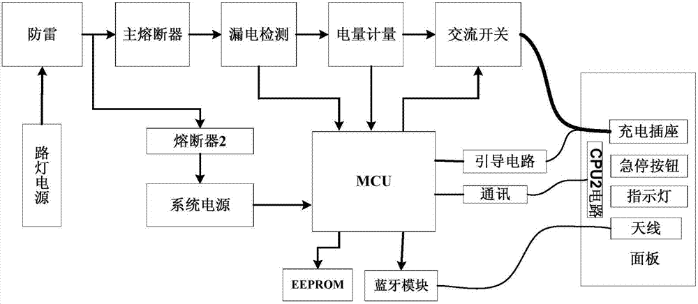
[0048] Such as figure 1 As shown, the light pole charging pile provided by the present invention includes two parts: the charging pile core controller and the automatic security output box. The core controller of the charging pile is installed in the hollow part of the light pole body, which is not only beneficial to the protection of this part, but also conducive to the transformation of the charging pile of the existing light pole; and the automatic security output box needs to be directly operated by the charging user For the part, the metal box body with a curved back panel is used to fit and hang outside the light pole, which is conducive to installation and user-friendly operation.

[0049] The first part is the core controller of the charging pile: including the power inlet port and port protection module, Bluetooth communication module, CPU intelligent control module,...


PUM


Abstract

The invention discloses a lamp post type charging pile. The lamp post type charging pile comprises a charging pile core controller and an automatic security output box. The charging pile core controller is mounted in a hollow portion of a lamp post body, and the automatic security output box is suspended outside the lamp post body in an attached manner by the aid of a metal box. The charging pile core controller comprises a CPU (central processing unit) intelligent control module, a power line inlet port and port protection module, a Bluetooth communication module, an output switchover execution module, an electric power measurement module, a guide and input signal isolation module, a leakage protection module and an output port overtemperature protection module. The automatic security output box comprises a CPU2 single-chip microcomputer, an automatic security locking valve, a charging output socket, a socket temperature sensing and regulating module, status indicator lamps, an emergency charging stop button and a Bluetooth antenna and is arranged in the metal box. The front portion of the metal box is provided with the automatic security locking valve, an operation panel is arranged on the rear portion of the automatic security locking valve, and the charging output socket, the emergency charging stop button and the status indicator lamps are all arranged on the operation panel.

Description

technical field [0001] The invention relates to a lamp post type charging pile, which belongs to the field of electronic technology. Background technique [0002] Where there are street lights on the street, there are light poles and public lighting power sources. The traditional role of light poles and lamps is mainly for public lighting at night, and most of the time from early morning to dusk, street lights are basically idle, and the power supply for power supply to street lights along the way There is also no current in the line. For power facilities, this practice of using almost one-third of the time and idling for two-thirds of the time is undoubtedly a great waste of resources. In the planning and construction of smart cities, the intelligent management of street lamps is an important aspect, but intelligent street lamp management requires the support of communication networks, and if a separate management network is only set up for street lamps, the amount of tran...

Claims


Application Information

Patent Timeline
Patent Type & Authority Patents(China)
IPC IPC(8): B60L11/18F21V33/00H02J7/00
CPCB60L53/31F21V33/00H02J7/0026H02J7/0027Y02T10/70Y02T10/7072Y02T90/12
Inventor 贺飞胡骅李跃
Owner JIANGSU ROBOT TECH DEV CO LTD
Learn More