Bi-directional dust collection system

A technology of dust collection system and flow direction, which is applied in the field of cleaning devices to achieve the effects of easy assembly, easy maintenance and high mechanical strength

Inactive Publication Date: 2016-08-24
ROYAL INDAL TECH CORP
View PDF7 Cites 3 Cited by
  • Summary
  • Abstract
  • Description
  • Claims
  • Application Information

AI Technical Summary

Problems solved by technology

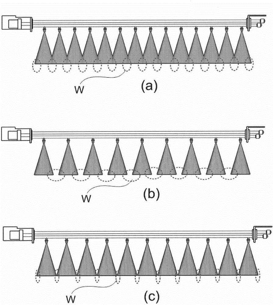
[0028] But described prior art 2, can refer to figure 1 (a), (a) figure illustrates the problem of the prior art patent application No. 10-2010-0052610 "composite cleaning device for cleaning electric dust collection device", that is, if the spray nozzle and the pipe of cleaning water If the ports are installed too close together, they will interfere with each other, resulting in a part where the water pressure or air pressure is too small (W)
but if figure 1 As shown in (b), if the installation is too wide, there will be a blank part (W) that cannot be touched by water pressure and air pressure.

Method used


Image

  • Bi-directional dust collection system
  • Bi-directional dust collection system
  • Bi-directional dust collection system

Examples


Embodiment Construction

[0097] The following detailed description of the invention refers to illustrations of specific implementations of the invention. In order to allow practitioners to refer to and execute, these execution examples are explained in great detail. The various implementations of the invention, while different, are understood to be not necessarily mutually exclusive. For example, an implementation example of a specific image, structure, and characteristic described here may be embodied as a different implementation example within the technical idea and scope of the invention. In addition, the position or arrangement of individual constituent elements in each embodiment can be changed without departing from the technical idea and scope of the invention. Therefore, the purpose of the following detailed description is not intended to be limiting, and the scope of the invention includes all claims identical to the claims of the claims and the claims attached thereto. Similar reference s...


PUM


Abstract

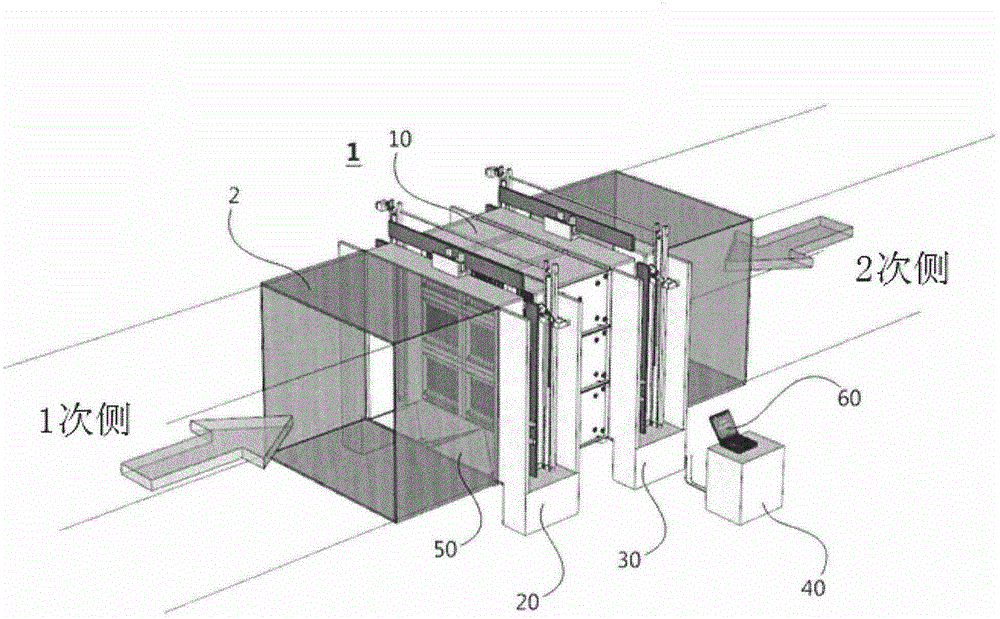
The present invention relates to a system for bi-directionally collecting dusts, in which the system comprises: an induction-voltage electrostatic filter consisting of a dust-collecting electrode which is grounded and an induction-voltage plate generating an induction-voltage; and a cleaning device for removing dusts or the like collected on the dust-collecting electrode. More specifically, a system further for bi-directionally collecting dusts comprises: an induction-voltage electrostatic filter part where a plurality of bi-directional induction-voltage electrostatic filters are coupled in a planar state; a primary and a secondary complex cleaning device part mounted at a front end and a rear end of the induction-voltage electrostatic filter part respectively; a supplying part connected to an air tube and a cleaning water tube of a complex spraying part of the primary and the secondary complex cleaning device part for supplying high-pressure air to the air tube and supplying high-pressure cleaning water to the cleaning water tube; a water-discharging part mounted at a lower portion of the induction-voltage electrostatic filter part and the primary and secondary complex cleaning device part for discharging collected materials of the dust-collecting electrode and the cleaning water; and a driving controlling part for controlling entire actions of the overall structure.

Description

technical field [0001] The invention relates to a two-way dust collection system for two-way adsorption of dust, dust and even water particles in the air. In particular, it relates to an induced voltage electrostatic filter composed of a grounded dust collecting electrode and an induced voltage plate for forming an induced voltage by the induced voltage, and also relates to a cleaning device for removing dust and the like adsorbed on the dust collecting electrode. Background technique [0002] Electrostatic precipitator (ESP) induced voltage electrostatic filter The principle of electrostatic dust collection is to charge the dust, dust and even water particles in the polluted gas, and the charged objects are captured by Coulomb force (electrostatic force). Pull it to the direction of the dust collecting pole, thus being trapped. [0003] The charging of the captured object is usually formed by the high voltage on the discharge electrode to form an electric field. Between th...

Claims


Application Information

Patent Timeline
IPC IPC(8): B03C3/02B03C3/78B03C3/80
CPCY02A50/2351B01D46/0032B01D46/44B03C3/12B03C3/155B03C3/78B01D46/681
Inventor 李承焕
Owner ROYAL INDAL TECH CORP
Why Eureka
Try Eureka