
Method for quickly establishing non-rotational symmetry lighting system model

A non-rotational symmetry lighting system technology, applied in the field of rapid establishment of lighting system models based on LED light sources, can solve problems such as limiting design freedom, increasing design complexity, and cumbersomeness, and achieves strong universality, automatic and rapid generation Effect

Active Publication Date: 2016-08-17
JIANGNAN UNIV
View PDF3 Cites 0 Cited by
  • Summary
  • Abstract
  • Description
  • Claims
  • Application Information

AI Technical Summary

Problems solved by technology

However, this kind of light distribution design scheme needs to use multiple softwares to operate together, which will increase the complexity of the design to a certain extent
[0003] In particular, when performing feedback optimization of the extended light source lighting system, the surface data needs to be continuously transferred in the three softwares, and the manual transfer of the traditional method greatly limits the freedom of design
Moreover, we can also find that it will be more cumbersome to construct a non-rotationally symmetrical mechanical model in modeling software, and the designer's work efficiency will drop sharply when iterative optimization

Method used


Image

  • Method for quickly establishing non-rotational symmetry lighting system model
  • Method for quickly establishing non-rotational symmetry lighting system model
  • Method for quickly establishing non-rotational symmetry lighting system model

Examples


Embodiment Construction

[0033] In order to describe the present invention in detail, the following will be described in conjunction with the accompanying drawings, but the examples described below are only used to explain the present invention.

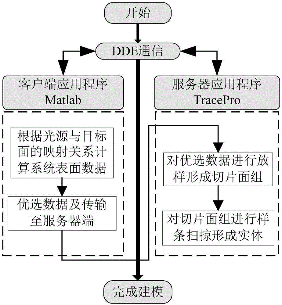
[0034] figure 1 It is the overall flow chart of the technical solution of the present invention, mainly using the DDE communication mechanism between Matlab and TracePro as the medium to organically combine the system surface calculation module and mechanical modeling. Among them, Matlab is responsible for data processing according to the mapping relationship, and TracePro is responsible for materializing the data by using schenme language and slicing method.

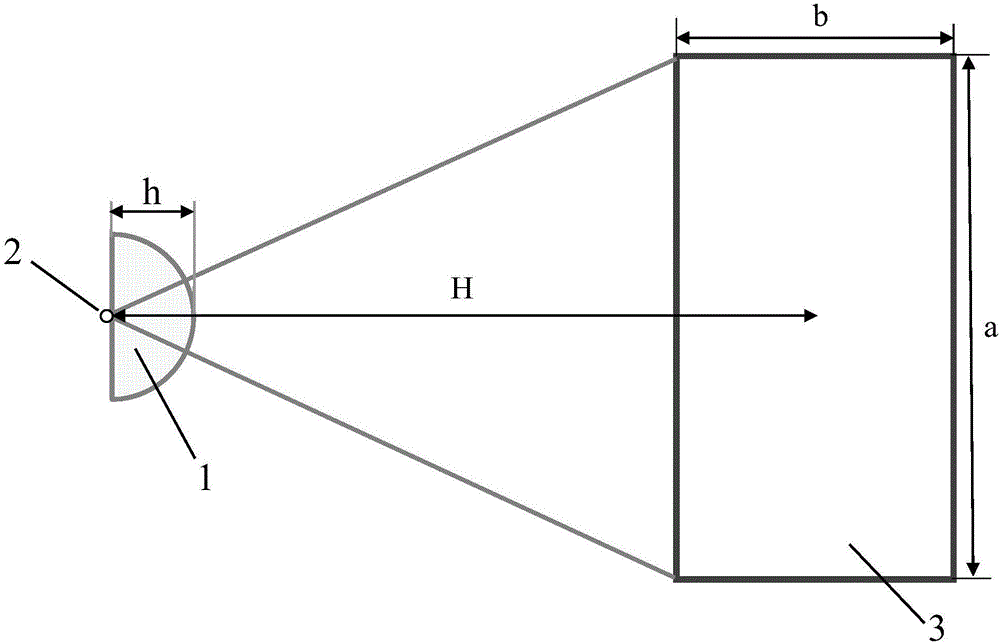
[0035] figure 2 One embodiment of the present invention is used: a uniform lens system of a rectangular target surface is used for rapid modeling, and the system belongs to a non-rotational symmetric structure. The uniform lens lighting system 1 in the embodiment is designed based on the LED point ...


PUM


Abstract

The invention discloses a method for quickly establishing a non-rotational symmetry lighting system model. The method comprises the steps of first utilizing a grid energy division principle to calculate point cloud data on the surface of a lighting system; establishing a channel between numerical analysis software Matlab and lighting simulation software TracePro through dynamic data exchange (DDE) communication, and transmitting the point cloud data to the TracePro; finally performing fitting on data points through TracePro macro languages, and utilizing sectioning to quickly form a solid model. The method has very high convenience and program ductility, the lighting system model designed according to the method can be generated automatically and quickly, and automatic optimization can be performed when a program module with respect to extension of iteration feedback of a light source lighting system is added.

Description

technical field [0001] The invention belongs to the field of non-imaging illumination, and in particular relates to a method for rapidly establishing an illumination system model based on an LED light source. Background technique [0002] At present, three steps are generally required for secondary optical light distribution design: Step 1, after constructing the mapping relationship between the light source and the target surface, calculate the numerical solution of the surface of the lighting system through numerical analysis software (such as Matlab). Step 2, import the numerical solution obtained in step 1 into a 3D modeling software (such as SolidWorks) to establish a solid model. Step 3, import the solid model into lighting simulation software (such as TracePro) for simulation analysis. However, this type of light distribution design scheme requires the use of multiple softwares for collaborative operation, which will increase the complexity of the design to a certain...

Claims


Application Information

Patent Timeline
IPC IPC(8): G06F17/50
CPCG06F30/367
Inventor 李潇钱维莹高淑梅谭叶青
Owner JIANGNAN UNIV
Learn More