
A detection method for passive resistance of electronic equipment

A passive resistance and detection method technology, applied in the direction of measuring resistance/reactance/impedance, measuring devices, measuring electrical variables, etc., can solve the problems of increasing the time of resistance value measurement and increasing the uncertainty of measurement values, so as to avoid errors , Improving the effect of data processing accuracy

Active Publication Date: 2018-07-06
BEIJING INST OF ELECTRONICS SYST ENG
View PDF3 Cites 0 Cited by
  • Summary
  • Abstract
  • Description
  • Claims
  • Application Information

AI Technical Summary

Problems solved by technology

In the performance measurement with many on-resistance paths at one time, the time for resistance value measurement is increased
In particular, the uncertainty of the measurement value due to multiple gear changes is increased

Method used


Image

  • A detection method for passive resistance of electronic equipment
  • A detection method for passive resistance of electronic equipment
  • A detection method for passive resistance of electronic equipment

Examples


Embodiment Construction

[0057] In order to illustrate the present invention more clearly, the present invention will be further described below in conjunction with preferred embodiments and accompanying drawings. Similar parts in the figures are denoted by the same reference numerals. Those skilled in the art should understand that the content specifically described below is illustrative rather than restrictive, and should not limit the protection scope of the present invention.

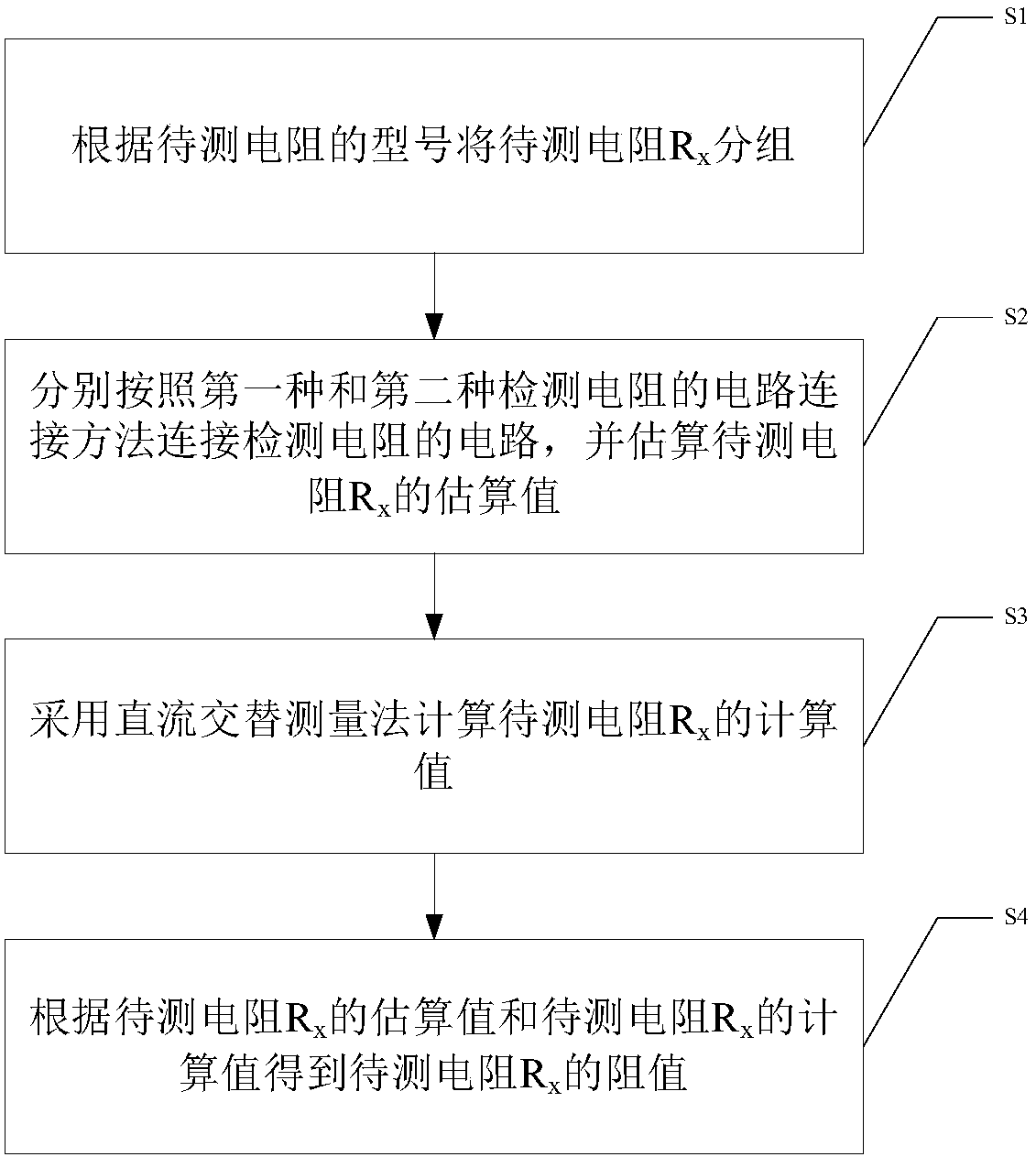
[0058] The detection method for the passive resistance of electronic equipment provided in this embodiment includes the following steps:

[0059] Step1. Group the resistors to be tested according to the model of the resistors to be tested;

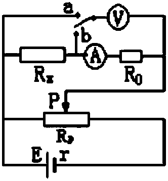
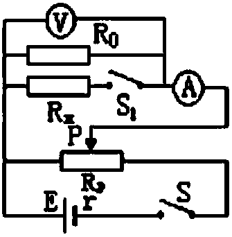
[0060] Step2. Connect the circuit of the detection resistor according to the first and second circuit connection methods of the detection resistor, and estimate the resistance R to be tested x the estimated value of

[0061] Step3. Calculate the resistance R to be measured by the DC ...


PUM


Abstract

The invention discloses a detection method of the passive resistance of an electronic device. According to the detection method, a reasonable tap position of an adjustable resistor is selected according to the theoretical range of testing resistance; collection and measurement are carried out at fixed time points; when resistance in different range intervals is measured, the adjustable resistor is switched to a different tap position; a direct-current alternating measurement method is adopted to further improve the accuracy of the resistance according to the selected tap position; and finally, with two methods mentioned in descriptions of the invention used in combination, the resistance value of the electronic device is calculated through adopting a curve fitting method. With the detection method provided by the technical schemes of the invention adopted, measurement accuracy and precision can be ensured. The detection method has a high engineering application value.

Description

technical field [0001] The invention relates to a detection method of resistance. More specifically, it relates to a detection method for passive resistance of electronic equipment. Background technique [0002] Passive resistance detection of electronic equipment Before the electronic equipment is powered on, check the various paths of the electronic equipment, check the paths between the signals and signal loops and the disconnection between the signals, and check the continuity between the signal and the casing situation, and display and transmit data. In the traditional passive resistance detection, a large gear is first selected for resistance testing, and if a small resistance value is detected, the corresponding gear is selected for resistance testing. In the performance measurement with many on-resistance paths at one time, the time for resistance value measurement is increased. In particular, the uncertainty of the measured value due to multiple gear changes is i...

Claims


Application Information

Patent Timeline
Patent Type & Authority Patents(China)
IPC IPC(8): G01R27/02
Inventor 王蕾蕾邱辉牛慧博
Owner BEIJING INST OF ELECTRONICS SYST ENG
Learn More