
Binary self-broken liquid-gas rock cracking pipe

A technology of cracking rock pipes and liquid gas, which is applied in the field of two-element self-breaking liquid and gas cracking rock pipes, can solve the problems of affecting rock cracking effects, insufficient high-pressure instantaneous pressure, and causing danger, so as to reduce equipment use costs and failure rates, The effect of improving work efficiency and increasing blasting pressure

Inactive Publication Date: 2016-08-17
唐山市堃岳裂岩设备有限公司
View PDF7 Cites 0 Cited by
  • Summary
  • Abstract
  • Description
  • Claims
  • Application Information

AI Technical Summary

Problems solved by technology

The existing equipment still adopts an integral pipe, and the shearing plate pressure relief method at the bottom of the pipe distributes the gas from bottom to top, resulting in slow pressure relief speed. and structural limitations) The flow rate of pressure relief gas is limited, so the relatively tightness of the rock hole to be cracked is poor, and the instantaneous pressure of the high pressure generated is insufficient, which seriously affects the rock cracking effect
At the same time as the pressure is released, the cut fragments will also fly tens of meters away, causing danger
When the existing cracked rock pipe is depressurized, due to the huge displacement force generated by the cracked rock mass, the pipe body of the cracked rock pipe is bent and the pipe head is broken, causing serious losses
And because the cracked rock pipes are connected by rigid connections, the middle and deep holes cannot be used and multiple rows cannot be operated at the same time, so the work efficiency is not high, and it is also a difficulty and bottleneck in the promotion of existing equipment

Method used


Image

  • Binary self-broken liquid-gas rock cracking pipe
  • Binary self-broken liquid-gas rock cracking pipe
  • Binary self-broken liquid-gas rock cracking pipe

Examples


Embodiment Construction

[0029] The present invention will be further described below in conjunction with the accompanying drawings and implementation examples.

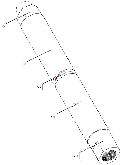
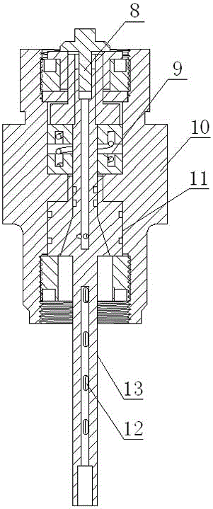
[0030] See attached Figure 1-8 , The rock cracking pipe disclosed in the present invention is a liquid-gas blasting pipe, which can be widely used in fields requiring safe blasting, and has high safety, strong blasting force, simple operation, high efficiency and low use cost.

[0031] The binary self-cutting liquid gas-cracking rock pipe disclosed by the present invention includes A\B unit pipe bodies, heat source pipes are arranged in the pipe bodies, and liquid-filled electrode heads and electrode tail seats are respectively installed at both ends of the pipe body. The tailstock is equipped with a K cathode electrode screw. The liquid-filled electrode head is connected to one end of the tube body of unit A through threads, the tube body A and tube B are connected through an overpressure energy release device, the tailstock of the electr...


PUM


Abstract

The invention provides a binary self-broken liquid-gas rock cracking pipe. The binary self-broken liquid-gas rock cracking pipe comprises a main pipe body. A heat source pipe is arranged in the main pipe body. The two ends of the main pipe body are provided with a self-locking type charging electrode tip and an electrode tailstock. The main pipe body is composed of a unit pipe A and a unit pipe B, wherein the unit pipe A and the unit pipe B are connected through an overpressure energy release device. The self-locking type charging electrode tip is connected with the unit pipe A, and a charging rod is arranged in the self-locking type charging electrode tip. The lower portion of the charging rod is arranged in the unit pipe A. The electrode tailstock is installed at the tail of the unit pipe B, and a cathode electrode screw K is arranged on the electrode tailstock. A blind installation mechanism is arranged in the main pipe body and comprises two umbrella-shaped electrodes arranged on the self-locking type charging electrode tip and the electrode tailstock, and the umbrella-shaped electrodes are connected with electrode rods at the two ends through telescopic electrode bodies. The heat source pipe is pressed between the two umbrella-shaped electrodes, so that the heat source pipe is fixed and is communicated with the electrodes. A column type electronic trigger pipe is arranged in the center of the heat source pipe. The overpressure energy releasing device is a hollow cylindrical barrel, and prestress tanks are separately arranged on the outer wall and the inner wall of the cylindrical barrel in a 120-degree tri-section arrangement mode.

Description

technical field [0001] The invention relates to a blasting equipment, in particular to a two-element self-breaking liquid and gas cracking rock pipe. Background technique [0002] At present, the technology of similar liquid gas cracking rock pipes produced in China originated from the Edox blasting tube in the United States in the early 1960s; this device is derived from the cleaning of pipeline obstructions and the pumping function of high-gas coal mines. In terms of design structure, the existing equipment has relatively large defects for rock mass blasting. The existing device lengthens the length and diameter of the cracking rock pipe on the basis of the original design to increase the liquid filling capacity, and adopts a quick connection on the connection, which improves the pressure relief pressure, and there is no substantial change in the structure. The existing equipment still adopts an integral pipe, and the shearing plate pressure relief method at the bottom of...

Claims


Application Information

Patent Timeline
Patent Type & Authority Applications(China)
IPC IPC(8): F42D1/00F42D3/04F42D5/00
CPCF42D1/00F42D3/04F42D5/00
Inventor 岳志存
Owner 唐山市堃岳裂岩设备有限公司
Learn More