Single-sliding-vane rotary displacement pump

A technology of rotary and volumetric pumps, which is applied in the direction of rotary piston pumps, rotary piston machines, rotary piston/swing piston pump components, etc. It can solve the problems of inability to form a sealed state, cumbersome manufacturing and processing, and affect the sealing performance, etc. problems, to achieve the effect of good sealing, wide range of uses and convenient maintenance

Active Publication Date: 2016-08-17
陈继业
View PDF5 Cites 1 Cited by
  • Summary
  • Abstract
  • Description
  • Claims
  • Application Information

AI Technical Summary

Problems solved by technology

Due to the unreasonable design of the inner ring curve of the cross section of the stator, when the rotor rotates, it is difficult for the two ends of the sliding vane to always adhere to the surface of the inner wall of the stator, and a sealed state cannot be formed. Especially when the rotor is running at low speed, due to the lack of sufficient centrifugal force guarantee, the sliding There will be a gap between the sheet and the inner wall of the stator
The sliding vane usually requires the assistance of springs or other devices to make both ends of the sliding vane stick to the inner wall surface of the stator, but the manufacturing and processing are cumbersome, and when the rotor is running at high speed, the spring will be squeezed by centrifugal force and affect the sealing performance
In summary, the existing single vane rotary volumetric pumps have deficiencies in terms of sealing performance, processing technology and use functions.

Method used


Image

  • Single-sliding-vane rotary displacement pump
  • Single-sliding-vane rotary displacement pump
  • Single-sliding-vane rotary displacement pump

Examples


Embodiment Construction

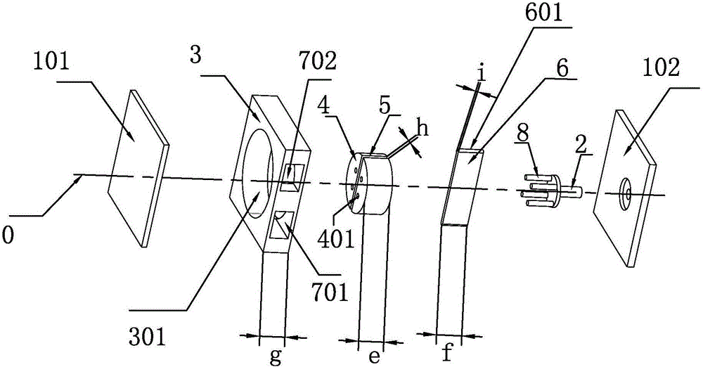
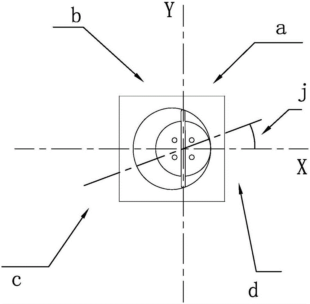
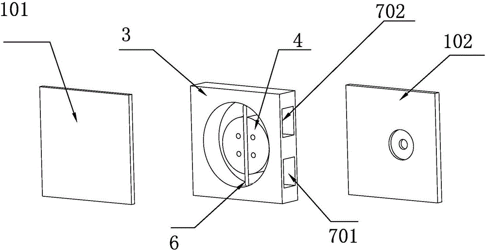
[0018] See attached figure 1 to attach image 3 , the present invention discloses a single vane rotary volumetric pump, a single vane rotary volumetric pump, comprising a front cavity splint 101, a rear cavity splint 102, a power shaft 2, a stator 3, a rotor 4, and a slide vane 6 , the feed port 701 and the discharge port 702, the front chamber splint 101 and the rear chamber splint 102 are respectively installed on the front and rear sides of the 3 stator, for sealing the stator 3; the axis of the power shaft 2 is the rotation axis 0; The section curve of the stator cavity 301 is a closed curve with a predetermined shape, and the section of the stator cavity 301 is perpendicular to the axis of rotation 0; Cut, the rotor 4 is cylindrical as a whole, the rotation axis 0 passes through the upper and lower centers of the rotor 4, the rotor 4 rotates around the rotation axis 0, and the rotor 4 is provided with a radially through slide slot 5 on the surface where the rotation axis...


PUM


Abstract

The invention relates to a single-sliding-vane rotary displacement pump which comprises cavity clamping plates, a power shaft, a stator, a rotor and a sliding vane, wherein the axis of the power shaft is a rotating axis, the cross section of a stator cavity is perpendicular to the rotating axis, the rotor is bias arranged in the stator cavity and is tangent with the stator cavity, a cross-section inner circling curve of the stator is formed by using any one point on the rotating axis passing by the stator cavity as an original point and establishing smooth transitional connection of all points in a rectangular coordinate system on a plane perpendicular to the rotating axis, the coordinate system divides the plane into four quadrants, the bottom surface radius of the rotor is R, the length of the sliding vane is 2S, an included angle is t, the t ranges from 0 to 90, and the points are obtained through a calculation formula. The length of a line section formed by any straight line passing by the original point and perpendicular to the rotating axis and two intersection points of the inner circling curve is always equal to the length of the sliding vane. By the adoption of the technical scheme, the single-sliding-vane rotary displacement pump has the advantages of being simple in manufacturing process, low in cost, good in sealing performance and suitable for high-speed and low-speed operation.

Description

technical field [0001] The invention relates to a single-vane rotary displacement pump. Background technique [0002] The single vane rotary volumetric pump in the prior art usually includes a stator, a rotor and a vane. The rotor is provided with a vane slot, and the vane is installed in the vane slot and can slide freely along the slot. Due to the unreasonable design of the inner ring curve of the cross section of the stator, when the rotor rotates, it is difficult for the two ends of the sliding vane to always stick to the surface of the inner wall of the stator, and cannot form a sealed state. Especially when the rotor is running at low speed, due to the lack of sufficient centrifugal force guarantee, the sliding A gap is formed between the sheet and the inner wall of the stator. Sliding vanes usually need the assistance of springs or other devices to make both ends of the sliding vane adhere to the inner wall surface of the stator, but the manufacturing and processing ...

Claims


Application Information

Patent Timeline
IPC IPC(8): F04C2/344F04C15/00F04C15/06
CPCF04C2/3446F04C15/00F04C15/06F04C2240/20F04C2250/20
Inventor 陈继业
Owner 陈继业
Why Eureka
Try Eureka