Rotating locating device adopting rotating support for rotating platform

A technology of a rotating platform and a positioning device, which is applied to the buildings, building types, buildings, etc. where cars are parked, can solve the problems of large inertia, heavy transport platform, and difficult mechanical action control, and achieve accurate action control and change the internal structure. Stress, fast response effect

Active Publication Date: 2016-08-17
王景保
View PDF7 Cites 0 Cited by
  • Summary
  • Abstract
  • Description
  • Claims
  • Application Information

AI Technical Summary

Problems solved by technology

[0002] The applicant has worked in the field of three-dimensional underground parking garages for decades, and found that it is difficult to control the position of the rotary platform when picking and placing vehicles in the three-dimensional garage. Therefore, the self-weight of the transport platform is very large, and it is difficult to control the mechanical action. Now the vehicle is required to be accessed at a fast speed, which leads to a large inertia, and at the same time, it is very difficult to align the rotating platform with the parking space, which makes the start and stop of the drive system difficult. It brings a large instantaneous load, which poses a great challenge to the reliability of the machine. Blindly increasing the driving power increases the speed of the equipment, but the precise alignment is more difficult. There is a gap between the fast access to the vehicle and the accurate alignment of the parking space. The relative contradiction brings great challenges to the reliability of the machinery. Improving the driving power is one way, but after the speed of access to the vehicle is accelerated, the accurate alignment of the parking space becomes a bottleneck, so technical difficulties have been encountered

Method used


Image

  • Rotating locating device adopting rotating support for rotating platform
  • Rotating locating device adopting rotating support for rotating platform
  • Rotating locating device adopting rotating support for rotating platform

Examples


Embodiment Construction

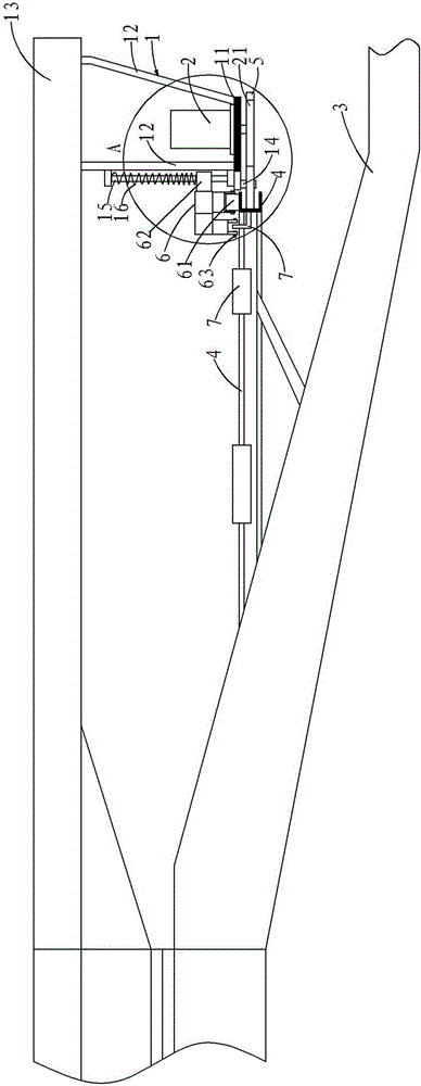
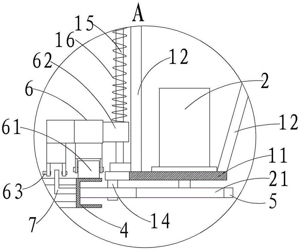
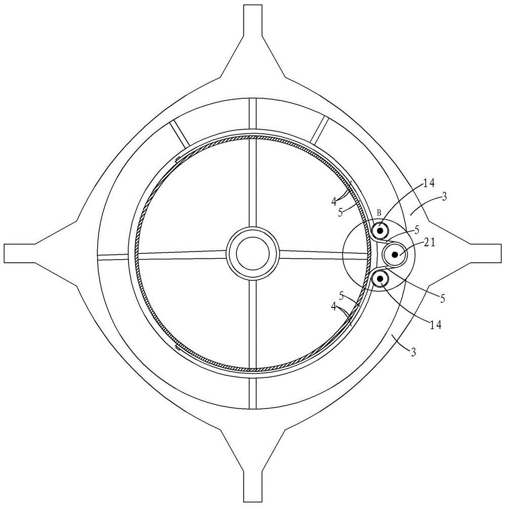
[0032] The following is attached Figure 1-6 The present invention is further described in detail.

[0033] as attached Figure 1-6 As shown, a rotary positioning device for a rotary support rotary platform includes a drive frame 1 arranged at the bottom of the rotary platform 13, a drive motor 2 arranged on the drive frame 1, a positioning frame 6 arranged on one side of the drive frame 1 and a set On the grooved rail 4 on the lifting platform 3, the grooved rail 4 is positioned at the lower side of the positioning frame 6, and the grooved rail 4 corresponds to the position of the driving end of the drive motor 2; the grooved rail 4 is an arc-shaped track and Corresponding to the running track of the drive frame 1, the groove rail 4 is a U-shaped groove body with an opening facing away from the center of the circle. The groove rail 4 is connected to the driving end of the drive motor 2 through a flexible traction belt, and the flexible traction belt The belt is arranged at ...


PUM


Abstract

The invention relates to a rotating locating device adopting rotating support for a rotating platform. The rotating locating device comprises a driving frame arranged at the bottom of the rotating platform, a driving motor arranged on the driving frame, a locating frame arranged on one side of the driving frame and a grooved rail arranged on a lifting platform, wherein the grooved rail is located on the lower side of the locating frame, corresponds to the position of a driving end of the driving motor, is an arc-shaped track, corresponds to the movement path of the driving frame, and adopts a U-shaped groove body with an opening opposite to the circle center. With adoption of the technical scheme, driving connection of the rotating platform and the lifting platform is transferred to the edge of the rotating platform, therefore, internal stress of mechanical driving can be changed effectively, a low-power driving motor can be assembled, a driving motor with high rotating speed and low torque can be also mounted, rapid response of the rotating platform can be realized, small-stress driving is realized, a locating point can be close to the parking space, and an action to reach the parking space is accurately controlled.

Description

technical field [0001] The invention belongs to the field of three-dimensional mechanical garages, and in particular relates to a rotary positioning device for a rotary support rotary platform. Background technique [0002] The applicant has worked in the field of three-dimensional underground parking garages for decades, and found that it is difficult to control the position of the rotary platform when picking and placing vehicles in the three-dimensional garage. Therefore, the self-weight of the transport platform is very large, and it is difficult to control the mechanical action. Now the vehicle is required to be accessed at a fast speed. The high speed leads to large inertia, and at the same time, it is very difficult to align the rotating platform with the parking space, which makes the start and stop of the drive system difficult. It brings a large instantaneous load, which poses a great challenge to the reliability of the machine. Blindly increasing the driving power...

Claims


Application Information

Patent Timeline
Patent Type & Authority Applications(China)
IPC IPC(8): E04H6/28
CPCE04H6/282
Inventor 王景保王洋
Owner 王景保
Why Eureka
Try Eureka