
Spoiler pipeline type fish way and design method

A technology of baffles and fishways, which is applied in water conservancy projects, sea area projects, climate change adaptation, etc., can solve problems such as poor adaptability and small flow rate capacity, and achieve the effects of low cost, reduced barrier impact, and reduced construction costs

Active Publication Date: 2016-08-17
CHINA INST OF WATER RESOURCES & HYDROPOWER RES
View PDF8 Cites 2 Cited by
  • Summary
  • Abstract
  • Description
  • Claims
  • Application Information

AI Technical Summary

Problems solved by technology

For some target fish species that are small in size, low in ability to overcome flow velocity, and poor in adaptability to complex flow regimes, such as eels, crabs, "four major fish", saury, perch, etc., there are limitations in the existing fishway design. Referring to the fishway design standards for large fish species, it turns out that there are very few successful fishways in actual operation

Method used


Image

  • Spoiler pipeline type fish way and design method
  • Spoiler pipeline type fish way and design method
  • Spoiler pipeline type fish way and design method

Examples


Embodiment 1

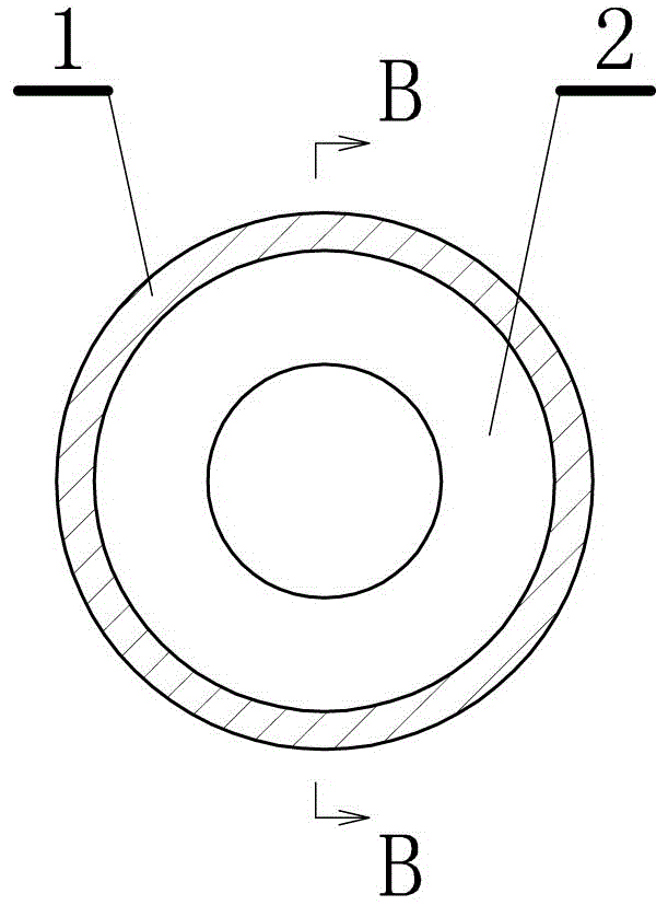
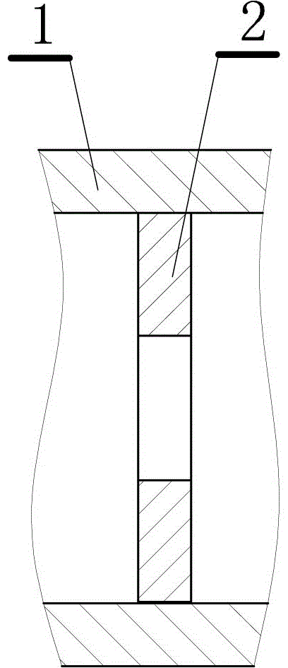
[0034] Present embodiment is a kind of baffle pipe type fishway, as figure 1 shown. This embodiment includes: a pipe-shaped main body 1 connecting the upstream and downstream of the water conservancy project, and baffles 2 are evenly arranged along the inside of the pipe-shaped main body.

[0035] In this embodiment, the sudden change of the streamline of the water flow at the baffle plate and the generation of annular shrinking water flow on the upstream and downstream sides of the baffle plate develop into a vortex zone in the area between the shrinking water flow and the periphery of the fishway pipe body. The strong turbulence of the water flow in the vortex area, the mixing and the shearing action inside the water flow cause shear friction and collision inside the water flow, which converts part of the kinetic energy into heat energy, thereby achieving the purpose of reducing the flow velocity.

[0036] The cross-sectional shape of the pipeline can be circular, square, ...

Embodiment 2

[0042] This embodiment is an improvement of Embodiment 1, and it is a refinement of the tube-shaped main body in Embodiment 1. The cross-sectional shape of the tube-shaped main body described in this embodiment and perpendicular to the water flow direction is one of a circle, a rectangle, and a regular polygon. .

[0043] figure 2 It is a schematic diagram of a pipe body with a circular cross-section, in which the baffle is ring-shaped. The cross-sectional shape of the pipe body can be arbitrarily selected according to needs.

Embodiment 3

[0045]This embodiment is an improvement of the above embodiment, and is a refinement of the above embodiment regarding the baffle. The spoiler described in this embodiment is an annular spoiler.

[0046] The so-called annular baffle actually forms an annular baffle facility on the pipe wall to reduce the flow velocity of the water, so that fish can migrate. Since the flow blocking facilities can have various shapes, the flow blocking plate described in this embodiment can also have various shapes, for example, a triangular flow blocking plate similar to a triangular pier.


PUM


Abstract

The invention relates to a spoiler pipeline type fish way and a design method. The spoiler pipeline type fish way comprises a tubular body connected with the upstream and downstream of hydraulic engineering, wherein spoilers are uniformly arranged along the interior of the tubular body. The fish way tubular body is a tube which can be buried in the ground or fixed in the air. The tubes can be even vertically arranged, and the characteristic cannot be realized by other types of fish ways. The tubes can be formed by prefabrication before installation. The prefabrication cost is low, and field installation is very simple, so that the construction cost of the fish way is much lower than that of common fish ways. The fish way reduces the blocking effect on fishes by hydraulic engineering, reduces the construction cost, improves the fish pass efficiency, and has significance on protection and restoration of river ecological environment.

Description

technical field [0001] The invention relates to a baffle pipe-type fishway and a design method thereof, and is an environmental protection hydraulic facility and a design method, and is an environmental protection hydraulic facility and a design method for water flow engineering such as a reservoir. Background technique [0002] As an important facility for migratory fish and other aquatic animals to pass through artificial dams, fishways play an important role in coordinating the contradiction between dam construction and the ecological environment. Fishways are set on water retaining structures to meet the needs of migratory fish Requirements for upstream or downstream. Existing fishways include various forms of fishways such as pool type, vertical slot type, baffle type, simple type, fish ladder and fish gate. Each fishway forms different water flow conditions to adapt to the smooth passage of different fish. Dams and other water retaining structures. Fishway is a multi...

Claims


Application Information

Patent Timeline
IPC IPC(8): E02B8/08
CPCY02A20/402Y02A40/60E02B8/08
Inventor 白音包力皋陈兴茹许凤冉穆祥鹏刘慧李想
Owner CHINA INST OF WATER RESOURCES & HYDROPOWER RES
Learn More