Wire feeding and storing device of detonator tube
A detonating tube and wire storage technology, which is applied in the directions of transportation and packaging, delivery of filamentous materials, thin material processing, etc., can solve the problem of prone to accumulation or temporary shortage, the detonating tube cannot be automatically cut to a fixed length, and it is not easy to take the initiative To prevent the accumulation or temporary shortage of detonating tubes, save work intensity and work time, and save production costs
- Summary
- Abstract
- Description
- Claims
- Application Information
AI Technical Summary
Problems solved by technology
Method used
Image

Examples
specific Embodiment approach 1
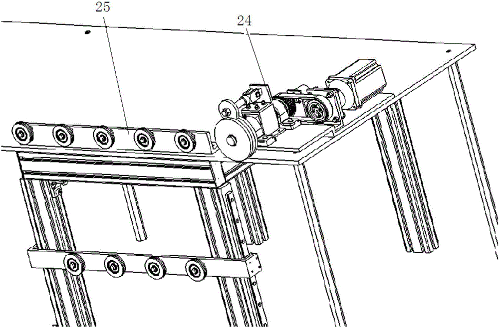
[0016] Specific implementation mode one: combine Figure 1 to Figure 3 Explain that a nonel wire feeding and wire storage device in this embodiment includes a traction wire feeding mechanism 24 and a wire storage buffer mechanism 25, and the traction wire feeding mechanism 24 and the wire storage buffer mechanism 25 are respectively installed on the operating platform 17;
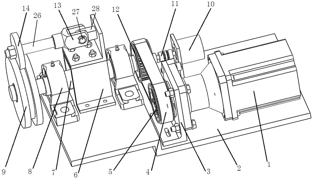
[0017] The traction wire feeding mechanism 24 includes a stepping motor 1, a base 2, a synchronous belt 4, a driving pulley 5, a driving spindle 7, a wire passing guide wheel 9, a rotary encoder 10, a driving pulley 12 and a crimping wheel 14, and the base 2 Fixed on the upper surface of the operating platform 17, the stepping motor 1 is arranged on the base 2, the driving pulley 5 is fixed on the output shaft of the stepping motor 1, the driving pulley 5 is connected with the driving pulley 12 through the synchronous belt 4 Connection, the wire passing guide wheel 9 is arranged on the front end of the driv...
specific Embodiment approach 2
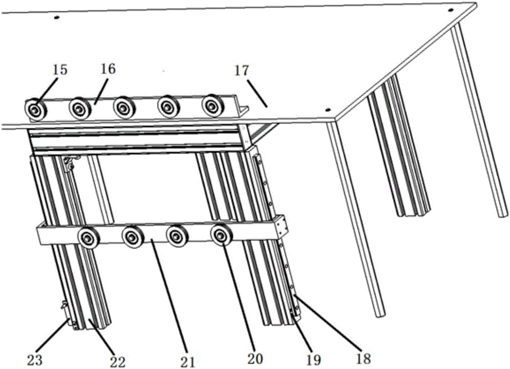
[0020] Specific implementation mode two: combination figure 1 with image 3 It should be noted that the wire storage buffer mechanism 25 in this embodiment further includes a limit screw 19 , and the limit screw 19 is fixedly connected to the lower end of the support frame 22 . Other compositions and connection methods are the same as those in Embodiment 1.
[0021] The limit screw 19 is designed in this way to carry out two-level limit on the floating wire storage wheel 20, which can ensure that the floating wire storage wheel 20 is always on the linear guide rail 18 when special working conditions are encountered.
specific Embodiment approach 3
[0022] Specific implementation mode three: combination figure 1 with figure 2 To illustrate, the front end of the stepping motor 1 in this embodiment is connected with a reducer, and the reducer is fixedly connected to the base 2 through the reducer support 3 . Other compositions and connection modes are the same as those in Embodiment 1 or 2.
PUM
 Abstract
Description
Claims
Application Information
 - R&D
- Intellectual Property
- Life Sciences
- Materials
- Tech Scout
- Unparalleled Data Quality
- Higher Quality Content
- 60% Fewer Hallucinations
Browse by: Latest US Patents, China's latest patents, Technical Efficacy Thesaurus, Application Domain, Technology Topic, Popular Technical Reports.
© 2025 PatSnap. All rights reserved.Legal|Privacy policy|Modern Slavery Act Transparency Statement|Sitemap|About US| Contact US: help@patsnap.com