Assembly line for gas valves

An assembly line and valve technology, applied in assembly machines, metal processing equipment, manufacturing tools, etc., can solve problems such as difficult to control quality stability, low work efficiency, and high product repair rate

Pending Publication Date: 2016-08-17
NANJING AIMEIQING INTELLIGENT TECH CO LTD
View PDF0 Cites 20 Cited by
  • Summary
  • Abstract
  • Description
  • Claims
  • Application Information

AI Technical Summary

Problems solved by technology

Gas valves are in great demand in both industry and household use. Traditional gas valve production requires a large amount of manual collaboration to complete. The labor intensity of workers is high, work efficiency is low, product repair rates are high, and quality stability is difficult to control, which affects the entire industry. Large-scale production of gas valves
There is still a lack of fully automatic assembly lines suitable for gas valves in the prior art, mainly for the assembly lines of valves with relatively simple structures and assembly procedures, such as Figure 15 and Figure 16 As shown, the gas valve assembled by the present invention includes: a valve body 19, a shutter 196 is nested in the valve body 19, and a cork 1911, a large screw 193, a small screw 194, a short Copper joint 192, long copper joint 191 and solenoid valve 198, fine-tuning spool 197 and spool assembly 195 are installed above valve body 19, switch shaft assembly 199 is installed above spool assembly 195, and cover plate is set on the outside of switch shaft assembly 199 1910

Method used


Image

  • Assembly line for gas valves
  • Assembly line for gas valves
  • Assembly line for gas valves

Examples


Embodiment Construction

[0032] Such as figure 1As shown, the gas valve assembly line of the present invention includes a frame 1, on which an assembly main line 13 is installed, and the following stations are sequentially arranged on the assembly main line 13: the valve body front feeding station 2, the body dust suction station 3. Closed sub-direction identification and oiling station 4. Cork identification and assembly station 5. Small screw locking station, large screw locking station, short copper joint locking station 6, long copper joint locking post Position 7. Solenoid valve assembly and locking station 8. Fine-tuning spool assembly and locking station 9. Valve core assembly assembly station 10. Switch shaft assembly assembly station 11. Cover plate assembly and locking station and finished product unloading Bit 12.

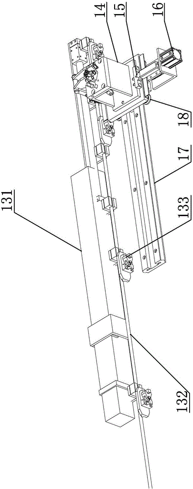
[0033] Such as figure 2 As shown, the main assembly line 13 includes a servo motor, a linear module 131 , an accompanying fixture 14 , a secondary positioning mechanism and ...


PUM


Abstract

The invention discloses an assembly line for gas valves, relates to an industrial assembly line for assembling gas valves, and aims to provide a full-automatic valve assembly line capable of improving the assembling efficiency of the gas valves and promoting large-scale production. The assembly line for the gas valves comprises a rack, wherein a main slide is arranged on the rack, a main assembly line is mounted on the rack, a pallet capable of moving horizontally is arranged on the main assembly line and is used for fixing valve bodies of the valves, and following stations are sequentially arranged on the main assembly line: a valve body front feeding station, a body dust collection station, a closed direction-distinguishing and oiling station, a closed oiling and rotating station, a cock direction-distinguishing and assembling station, a small screw locking station, a large screw locking station, a short copper joint locking station, a long copper joint locking station, an electromagnetic valve assembling and locking station, a fine-adjustment valve core assembling and locking station, a valve core assembly assembling station, a switch axle assembly assembling station, a cover plate assembling and locking station and a finished product discharging station.

Description

technical field [0001] The invention relates to an industrial assembly line, in particular to an assembly line for assembling gas valves. Background technique [0002] Gas valve is a common product in the industry, used to cut off, connect and adjust the gas in the pipeline, with good control characteristics and sealing performance; suitable for city gas, liquefied petroleum gas, natural gas, oxygen, etc. On the gas medium pipeline. Gas valves are in great demand in both industry and household use. Traditional gas valve production requires a large amount of manual collaboration to complete. The labor intensity of workers is high, work efficiency is low, product repair rates are high, and quality stability is difficult to control, which affects the entire industry. Large-scale production of gas valves. There is still a lack of fully automatic assembly lines suitable for gas valves in the prior art, mainly for the assembly lines of valves with relatively simple structures an...

Claims


Application Information

Patent Timeline
IPC IPC(8): B23P21/00
CPCB23P21/004
Inventor 张伟王飞飞李双林罗勇朱华
Owner NANJING AIMEIQING INTELLIGENT TECH CO LTD
Why Eureka
Try Eureka