
Loading and unloading device for lathe

A technology for loading and unloading materials and lathes, which is applied in metal processing and other directions, can solve problems such as waste, unstable product quality, and differences in workpiece processing, and achieve the effect of reducing labor load

Active Publication Date: 2019-01-22
HUBEI UNIV OF ARTS & SCI +2
View PDF5 Cites 7 Cited by
  • Summary
  • Abstract
  • Description
  • Claims
  • Application Information

AI Technical Summary

Problems solved by technology

Although the manual loading and unloading method can complete the processing of the workpiece, the labor intensity of the operator is high. In order to meet the demand of production output, the operator has to repeat thousands of loading and unloading actions every day, which is a great test for the operator.
Furthermore, manual loading and unloading relies too much on the operator, and it is easy to cause occupation and waste of human resources, and because there will be deviations in the placement of workpieces during manual loading, it will also cause problems in workpiece processing. difference, so that the instability of product quality

Method used


Image

  • Loading and unloading device for lathe
  • Loading and unloading device for lathe
  • Loading and unloading device for lathe

Examples


Embodiment Construction

[0033] In order to make the purpose, technical solutions and advantages of the embodiments of the present invention clearer, the technical solutions in the embodiments of the present invention will be clearly and completely described below in conjunction with the drawings in the embodiments of the present invention. Obviously, the described embodiments It is a part of embodiments of the present invention, but not all embodiments. The components of the embodiments of the invention generally described and illustrated in the figures herein may be arranged and designed in a variety of different configurations.

[0034] Accordingly, the following detailed description of the embodiments of the invention provided in the accompanying drawings is not intended to limit the scope of the claimed invention, but merely represents selected embodiments of the invention. Based on the embodiments of the present invention, all other embodiments obtained by persons of ordinary skill in the art wi...


PUM


Abstract

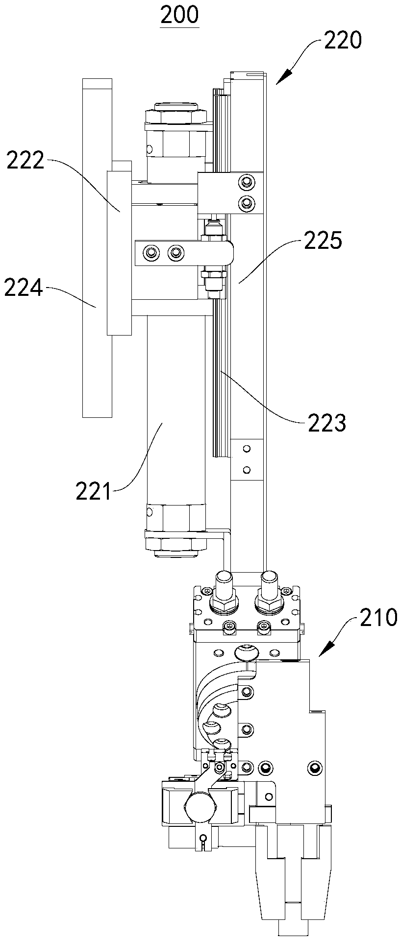
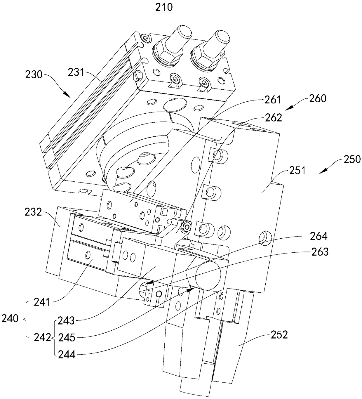
The invention relates to the technical field of automatic equipment, in particular to a loading and unloading device for a lathe. The loading and unloading device comprises a lathe body, a first horizontal movement module, a second horizontal movement module, a manipulator mechanism and a tray. The first horizontal movement module and the second horizontal movement module are fixedly arranged on the lathe body, included angles are formed between the first horizontal movement module and the second horizontal movement module, and the second horizontal movement module is arranged below the firsthorizontal movement module at intervals along the vertical direction; the manipulator mechanism is in transmission connection with the first horizontal movement module, and the first horizontal movement module is configured in such a manner that the manipulator mechanism can be driven by the first horizontal movement module to move along first directions; the tray is in transmission connection with the second horizontal movement module, and the second horizontal movement module is configured in such a manner that the tray can be driven by the second horizontal movement module to move along second directions. The loading and unloading device has the advantages that the amounts of labor of operators can be reduced, and the workpiece feeding and discharging speeds can be increased.

Description

technical field [0001] The invention relates to the technical field of automation equipment, in particular to a lathe loading and unloading device. Background technique [0002] CNC lathes and turning centers are high-precision, high-efficiency automated machine tools. Equipped with a multi-station turret or a power turret, the machine tool has a wide range of processing performance, and can process complex workpieces such as straight cylinders, oblique cylinders, arcs, and various threads, grooves, worms, etc., with linear interpolation, arc Various compensation functions are interpolated, and it has played a good economic effect in the mass production of complex parts. [0003] However, the prior art equipment generally adopts manual loading and unloading of CNC lathe processing workpieces when in use. The operator puts a single blank workpiece into the CNC lathe for processing, takes it out after processing, and then repeats the loading. this loop. Although the manual ...

Claims


Application Information

Patent Timeline
Patent Type & Authority Applications(China)
IPC IPC(8): B23B15/00
CPCB23Q7/046B23Q7/10
Inventor 李波谭宝剑秦慈超刘克非陈国华
Owner HUBEI UNIV OF ARTS & SCI
Learn More