
A Simple CNC Servo Screw Grinding Device

A screw and simple technology, applied in the field of thread grinding devices, can solve the problems of high price, high labor cost and high processing cost of CNC thread grinder, and achieve the effect of simple structure, improved efficiency and low price

Active Publication Date: 2017-11-03
宁波和鑫光电科技有限公司
View PDF9 Cites 0 Cited by
  • Summary
  • Abstract
  • Description
  • Claims
  • Application Information

AI Technical Summary

Problems solved by technology

[0003] In the prior art, the manual grinding machine and the CNC thread grinding machine are used for precision thread grinding of the workpiece; the manual grinding machine is a purely mechanical device, and it must be equipped with a proportioned hanging wheel set corresponding to the screw pitch of the workpiece to drive the workpiece to spiral through the transmission screw. For grinding processing, the proportional hanging wheel group and the transmission screw are driven by manual shaking of the handwheel during work. When processing workpieces with different thread pitches, the proportional hanging wheel group needs to be replaced frequently, which is low in efficiency and high in labor costs; CNC Due to the high price and high cost of thread grinding machines, the processing cost of mass production is high; therefore, the existing technology has the problems and shortcomings of low efficiency and high cost

Method used


Image

  • A Simple CNC Servo Screw Grinding Device
  • A Simple CNC Servo Screw Grinding Device
  • A Simple CNC Servo Screw Grinding Device

Examples


Embodiment Construction

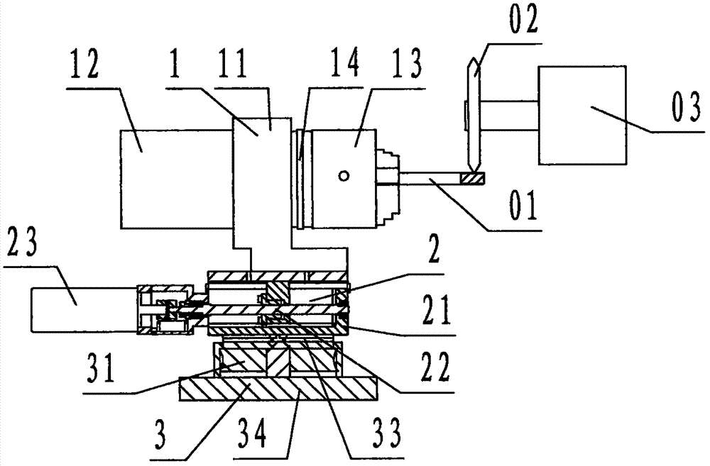
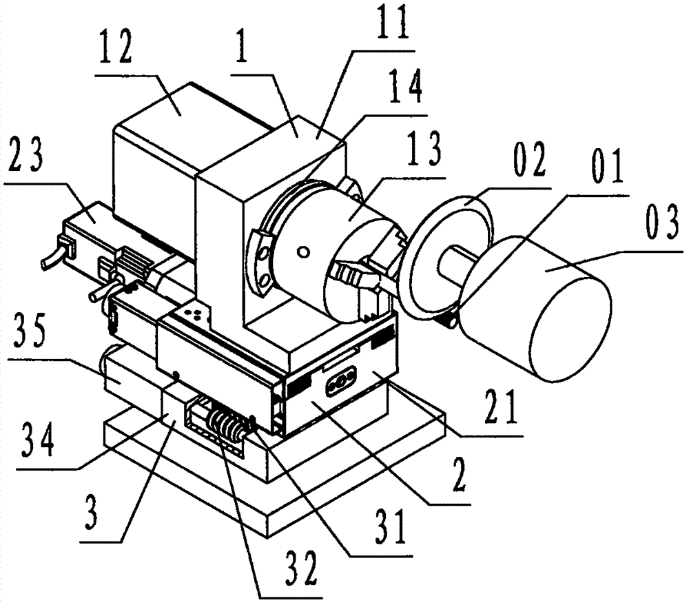
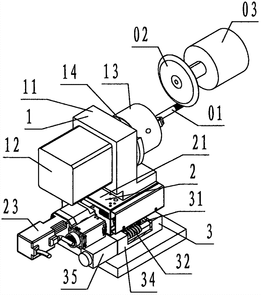
[0023] refer to Figure 1 ~ Figure 3 , a simple numerically controlled servo screw grinding device of the present invention, including a rotating mechanism 1, a reciprocating mechanism 2, and a plane indexing table 3, wherein: the rotating mechanism 1 is composed of a base A 11, a servo motor 12 and a clamp 13 , the A base 11 is provided with an upwardly protruding wallboard on the left, a base protruding upwardly to the right below, and an L-shaped block steel member. The center of the wallboard of the A base 11 is provided with left and right A connecting shaft 14 that passes through the wallboard and is used to transmit rotational motion; the clamp 13 is a three-jaw self-centering chuck; the A servo motor 12 is fixed on the left side of the A base 11, and the clamp 13 is located on the A base On the right side of the seat 11, the output end of the A servo motor 12 is connected to the fixture 13 through the connecting shaft 14;

[0024] The reciprocating mechanism 2 is comp...


PUM


Abstract

The invention discloses a simple numerically-controlled servo thread grinding device for a screw rod. The device comprises a rotating mechanism (1), a reciprocating mechanism (2) and a plane dividing platform (3); wherein the rotating mechanism is provided with an A base, an A servo motor and a clamp; the reciprocating mechanism is provided with a B dragging plate pair, a screw rod pair and a B servo motor; the plane dividing platform is provided with a worm wheel, a worm, a rotating platform, a C base and a C servo motor; the rotating mechanism is positioned on the upper surface of the reciprocating mechanism, and the reciprocating mechanism is positioned on the upper surface of the plane dividing platform; when in work, the device is mounted on a plane grinding machine, a workpiece is clamped at the clamp, a grinding wheel is mounted at a grinding head of the plane grinding machine, and an external numerical controller performs control; the plane dividing platform performs plane rotating in order to determine a helical angle of the thread, then the rotating mechanism rotates, and the reciprocating mechanism horizontally reciprocates, and thus the workpiece performs reciprocal helical movement; the grinding wheel performs rotating rather than space moving. According to the technical scheme, the device has the advantages that the grinding wheel is used for grinding the thread of the workpiece, so that the purposes of improving the processing efficiency and decreasing the cost of thread grinding processing can be achieved.

Description

technical field [0001] The invention relates to a thread grinding device, in particular to a simple CNC servo screw grinding device which is installed on a surface grinder and used for precision grinding and processing screw teeth. Background technique [0002] Grinding refers to the precision grinding process of the thread of precision screw products; for precision screw products, after milling or turning the thread blank shape of the formed screw, it is necessary to further perform precision grinding on the thread, which will be left below The screw workpiece that has grinding allowance and needs to be ground and processed is called workpiece for short. [0003] In the prior art, the manual grinding machine and the CNC thread grinding machine are used for precision thread grinding of the workpiece; the manual grinding machine is a purely mechanical device, and it must be equipped with a proportioned hanging wheel set corresponding to the screw pitch of the workpiece to dri...

Claims


Application Information

Patent Timeline
Patent Type & Authority Patents(China)
IPC IPC(8): B23G1/36B23G11/00B24B41/06
CPCB23G1/36B23G11/00B24B41/06
Inventor 杨宗烜
Owner 宁波和鑫光电科技有限公司
Learn More