
Controllable annular spring and detachable pot cover lifting handle with the same

An annular spring, detachable technology, applied in the field of detachable pot lid handle, can solve the problem of uncontrollable snap ring spring, and achieve the effects of convenient use, stable connection and simple structure

Inactive Publication Date: 2016-08-17
盛明星
View PDF2 Cites 4 Cited by
  • Summary
  • Abstract
  • Description
  • Claims
  • Application Information

AI Technical Summary

Problems solved by technology

[0004] In order to overcome the various problems of the existing handle design of the pot lid, to facilitate storage and transportation, and to prevent burns during use, the existing buckle ring spring is uncontrollable.

Method used


Image

  • Controllable annular spring and detachable pot cover lifting handle with the same
  • Controllable annular spring and detachable pot cover lifting handle with the same
  • Controllable annular spring and detachable pot cover lifting handle with the same

Examples


Embodiment 1

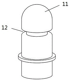
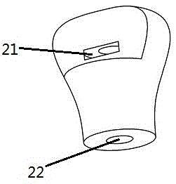
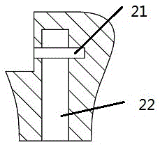
[0017] Example 1, figure 1 It is a schematic diagram of a cylindrical pin, which is cylindrical as a whole, 11. Arc-shaped head, 12. Groove, and the other end can be connected to the lid by common welding, threads, etc. figure 2 It is a schematic diagram of the female buckle body, 21. The spring placement space, 22. The cylindrical male buckle accommodation space. image 3 It is a sectional view of the female buckle body.

[0018] Figure 4 It is a schematic diagram of an ellipse spring, 41. ellipse major axis point, 42 ellipse minor axis point, when the long axis of both ends of the ellipse spring is squeezed, it will force 42. ellipse minor axis point to expand outward. Figure 5 It is a schematic diagram of an elliptical spring with a force-applying part, 51. The force-applying part, when the elliptical spring is loaded into the 21. spring placement space, the force applied by the 51. force-applying part will make the elliptical spring subject to 21. The spring is placed...

Embodiment 2

[0022] Embodiment 2, the controllable spring is the main point of the present invention, so the following description will focus on how the spring is controllable, and will not repeat others. Figure 7 It is a schematic diagram of a semi-circular and semi-elliptical spring. 71. The upper part of the semicircle and the lower part of 72. The ellipse, when the long axis point of the lower part of the ellipse is squeezed by force, the inner diameter of the spring is expanded. Tighter and has better stability than oval springs.

Embodiment 3

[0023] Example 3, Figure 8 Schematic diagram of a ring spring under force at both ends. 81. Forced parts at both ends, 82. Ring spring, when 81. Forced parts at both ends give 82. Ring spring a tangential force, 82. The inner diameter of the ring spring expands, which can control the opening and closing of the spring.


PUM


Abstract

A controllable annular spring and a detachable pot lid handle applied thereto, including a male buckle and a female buckle, the male buckle is cylindrical as a whole, one end adopts an arc design, and is provided with a groove; the female buckle is provided with a cylindrical male buckle The hole is provided with a controllable ring spring, which is characterized in that the controllable ring spring is in the shape of an ellipse as a whole, or a semicircle and a half ellipse, or a ring shape with force points at both ends, or one end is fixed and the other end is supported. Force ring. This structure makes the ring spring controllable by improving the buckle mode of the snap button, which is more convenient for people's life. When applied to the detachable pot cover, it is simpler than the existing design and easy to implement.

Description

technical field [0001] The invention relates to the technical field of cooking utensils, in particular to a controllable annular spring and a detachable pot lid handle used therefor. Background technique [0002] At present, in order to facilitate the lifting of the pot lid, a handle or a handle is usually provided on the pot lid. For example, Chinese Patent Authorization Bulletin No. CN20245742U discloses "a handle and a pot lid with the handle". The technology of the lid patent scheme One of the effects is that it is easy to hold and avoid scalding; the other is to form a head and a standing part at both ends of the holding part of the handle, so that when the pot lid leaves the pot body, it can be placed on the stove in an upright state. to maintain hygiene. However, this design has some shortcomings: first, the handle and the lid are permanently fixed, which is not easy to clean; second, it takes up too much space when storing and transporting the lid; third, when the h...

Claims


Application Information

Patent Timeline
Patent Type & Authority Applications(China)
IPC IPC(8): A47J36/06
CPCA47J36/06
Inventor 盛明星
Owner 盛明星
Learn More