
Radial magnetizing vacuum cleaning motor

A vacuum and clean technology, applied to synchronous motors with stationary armatures and rotating magnets, magnetic circuits, electrical components, etc., can solve problems such as few studies, no consideration at the same time, high cost, etc., to avoid organic pollution Effect

Active Publication Date: 2016-08-10
HARBIN INST OF TECH
View PDF9 Cites 1 Cited by
  • Summary
  • Abstract
  • Description
  • Claims
  • Application Information

AI Technical Summary

Problems solved by technology

As far as the current domestic and foreign markets are concerned, the German Phytron vacuum motor is widely used and the technology is relatively mature, but the cost is quite expensive, and the vacuum motor produced in China has not really reached the standard of vacuum products. The relevant research results are in the structure optimization , low temperature rise, high stability and cleanliness compared with foreign countries still have a certain gap, especially the design and use characteristics of motors in strong radiation, high vacuum and ultra-clean working environments are rarely studied
And the existing vacuum motors rarely follow the requirements of high cleanliness, and the occasions with cleanliness requirements are generally not used in vacuum environments, and high cleanliness and high vacuum are often not considered at the same time

Method used


Image

  • Radial magnetizing vacuum cleaning motor
  • Radial magnetizing vacuum cleaning motor
  • Radial magnetizing vacuum cleaning motor

Examples


Embodiment Construction

[0034] The present invention will be described in further detail below in conjunction with the accompanying drawings: the present embodiment is implemented on the premise of the technical solution of the present invention, and detailed implementation is provided, but the protection scope of the present invention is not limited to the following embodiments.

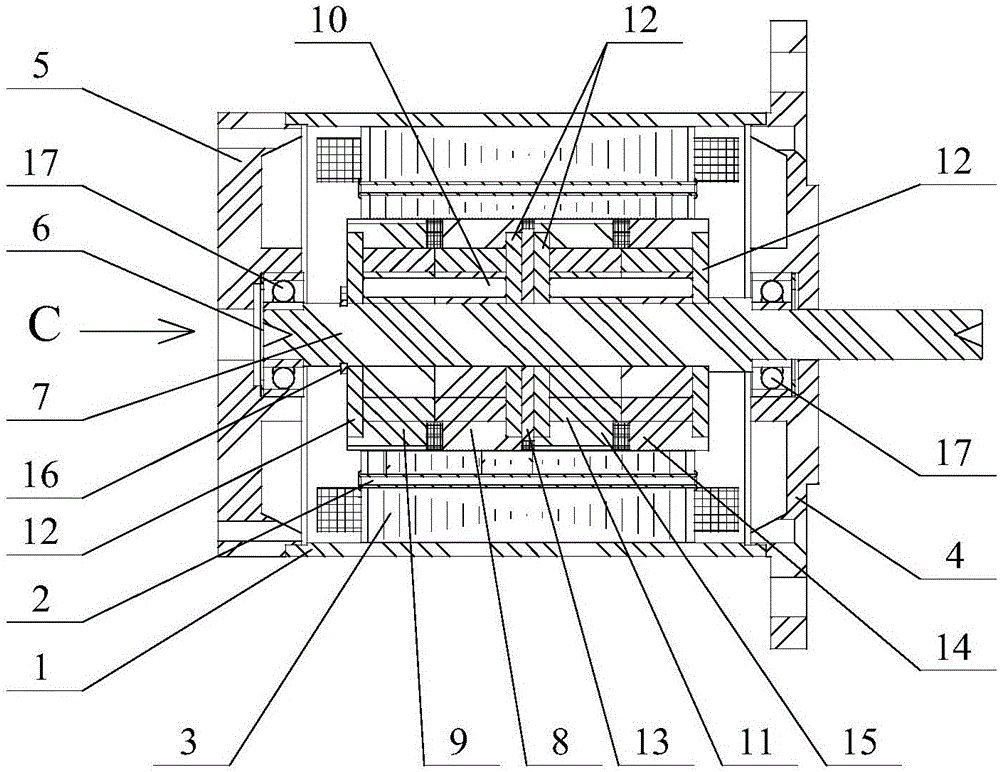
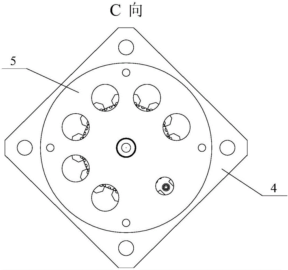
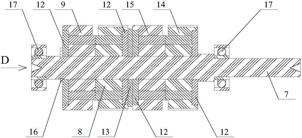
[0035] Such as Figure 1 to Figure 9As shown, a vacuum cleaning motor with radial magnetization involved in this embodiment includes: motor casing 1, stator punching rivets 2, stator punching 3, motor front end cover 4, motor rear end cover 5, bearing Spring pad 6, motor rotor shaft 7, motor rotor yoke three 8, motor rotor yoke four 9, motor rotor yoke positioning pin 10, rotor permanent magnet 11, rotor body retaining ring 12, rotor spacer ring 13, motor rotor yoke one 14, Motor rotor yoke 2 15, rotor shaft circlip 16 and ceramic deep groove ball bearing 17, the motor front end cover 4 is installed on the front end of the...


PUM

PropertyMeasurementUnit
Thicknessaaaaaaaaaa

Abstract

The invention provides a radial magnetizing vacuum cleaning motor, and belongs to the technical field of vacuum cleaning motor. A first motor rotor yoke and a second motor rotor yoke form a set, the outer side of the first motor rotor yoke and the outer side of the second motor rotor yoke are each provided with a rotor body retainer ring, and a rotor spacer ring is arranged between adjacent two rotor body retainer rings of the two sets of the motor rotor yokes. A rotor shaft snap spring is arranged on the rear portion of a rotor shaft of the motor, motor rotor yoke positioning pins are arranged on the third motor rotor yoke, the fourth motor rotor yoke, the first motor rotor yoke and the second motor rotor yoke, and rotor permanent magnet embedding ports are formed in the third motor rotor yoke, the fourth motor rotor yoke, the first motor rotor yoke and the second motor rotor yoke. Rotor permanent magnets are embedded in the rotor permanent magnet embedding ports. A bearing spring pad is arranged between a ceramic deep groove ball bearing at the rear end of the motor rotor shaft and a rear end cap of the motor, stator punching sheets are arranged between the motor rotor yokes and a motor casing, and stator punching sheet rivets are arranged on the stator punching sheets. The radial magnetizing vacuum cleaning motor is especially applicable to the aerospace field.

Description

technical field [0001] The invention relates to a vacuum clean motor with radial magnetization, and belongs to the technical field of vacuum clean motors. Background technique [0002] Vacuum clean motors refer to motors that can work under vacuum conditions and meet high cleanliness requirements. [0003] Vacuum clean motors mainly meet the requirements of two aspects, namely vacuum and cleanliness. Vacuum mainly refers to the use environment of the motor to meet a certain degree of vacuum, in which the motor can work normally, and the motor itself will not affect the vacuum environment. The cleanliness here means that in a vacuum environment, certain cleanliness requirements must be met, including not only dust, but also organic molecules. The motor will not affect the cleanliness of the environment during normal use, and can also meet normal work requirements. [0004] Therefore, the requirements for the use of vacuum clean motors are that they can work stably in ultra...

Claims


Application Information

Patent Timeline
IPC IPC(8): H02K21/14H02K5/173H02K1/27
CPCH02K1/2773H02K5/1732H02K21/14H02K2213/03
Inventor 陈家轩张庆春肖冬根包钢
Owner HARBIN INST OF TECH
Learn More