Antenna with reconfigurable beam direction and antenna array with reconfigurable beam scanning range
A beam direction and antenna technology, applied in the field of antenna arrays, can solve the problems of high cost, limited beam scanning range, complex structure of phased array antenna equipment, etc., and achieve low location restrictions, designable shape and height, and long length Effect
- Summary
- Abstract
- Description
- Claims
- Application Information
AI Technical Summary
Problems solved by technology
Method used
Image

Examples
Embodiment 1
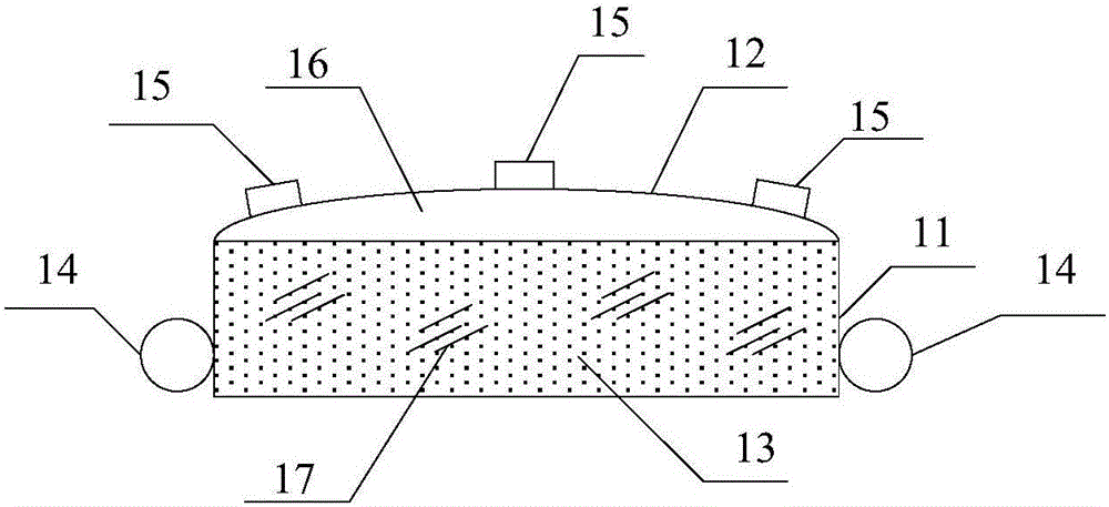
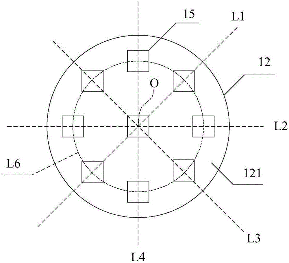
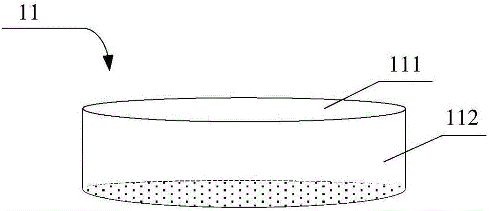
[0033] This embodiment provides an antenna with reconfigurable beam direction, see Figure 1~3 , the antenna includes: a body 11 , a first elastic film 12 , a first medium 13 , a curvature adjustment unit 14 and at least one antenna unit 15 . The first elastic membrane 12 is bonded to the body 11 , and the first elastic membrane 12 and the body 11 enclose to form a first variable volume cavity 16 . The first medium 13 is filled in the first variable volume cavity 16 , and the first elastic membrane 12 can be elastically deformed according to the volume or pressure change of the first medium 13 . The curvature adjustment unit 14 is used to change the curvature of the first elastic membrane 12 by changing the pressure or volume of the first medium 13 . At least one antenna unit 15 is glued on the outer surface 121 of the first elastic film 12 for receiving or sending wireless signals.
[0034] Further, the first medium is 13 liquid or colloid, such as water, dielectric or magn...
Embodiment 2
[0040] This embodiment provides another antenna with reconfigurable beam direction, such as Figure 4 As shown, the antenna includes: a body 21 , a first elastic film 22 , a first medium 23 , a curvature adjustment unit 24 , at least one antenna unit 25 and a second elastic film 27 . The first elastic membrane 22 and the second elastic membrane 27 are adhered to the body 21 , and the first elastic membrane 22 , the second elastic membrane 27 and the body 21 enclose the first variable volume cavity 26 . The first medium 23 is filled in the first variable volume cavity 26 , and the first elastic film 22 and the second elastic film 27 can be elastically deformed according to the volume or pressure change of the first medium 23 . The curvature adjusting unit 24 is used to change the curvature of the first elastic membrane 22 or the second elastic membrane 27 by changing the pressure or volume of the first medium 23 or the second elastic membrane 27 accordingly. At least one anten...
Embodiment 3
[0049] This embodiment provides a structural schematic diagram of a body, see Figure 8 , the main body 31 has a receiving portion, and a plurality of partitions 312 are arranged in the receiving portion, so as to divide the receiving portion into a plurality of sub-accommodating portions 313 having an open end 311 . A beam-reconfigurable antenna employing such a body includes multiple elastic membranes (combined with Figure 4 , such as elastic membranes 22 and 27). The plurality of first elastic films are respectively used to seal the open ends 311 of the plurality of subaccommodating parts, thereby forming a plurality of variable volume cavities (combined with Image 6 , such as variable volume cavities 262 and 261).
[0050] An antenna using the body may include a plurality of antenna units respectively disposed on a plurality of first elastic films. The formed multiple variable volume cavities can be filled with one or more media. According to the type of medium to be...
PUM
 Abstract
Description
Claims
Application Information
 - R&D
- Intellectual Property
- Life Sciences
- Materials
- Tech Scout
- Unparalleled Data Quality
- Higher Quality Content
- 60% Fewer Hallucinations
Browse by: Latest US Patents, China's latest patents, Technical Efficacy Thesaurus, Application Domain, Technology Topic, Popular Technical Reports.
© 2025 PatSnap. All rights reserved.Legal|Privacy policy|Modern Slavery Act Transparency Statement|Sitemap|About US| Contact US: help@patsnap.com