Cam rotor hydraulic motor for distributing oil in abdominal cavity

A cam rotor, hydraulic motor technology, applied in the direction of rotary piston engine, rotary or oscillating piston engine, machine/engine, etc., can solve the problem of processing difficulty and processing cost, increasing equipment volume and energy consumption, and difficult sealing problems. Solve and other problems to achieve the effect of easy processing, reduced volume, and effective sealing

Active Publication Date: 2016-08-10
王向军
View PDF6 Cites 0 Cited by
  • Summary
  • Abstract
  • Description
  • Claims
  • Application Information

AI Technical Summary

Problems solved by technology

[0002] At present, in hydraulic machines that require low-speed rotation, and at the same time set other components at the center of rotation or require simultaneous movement and other compound motions, the usual solution is to install another motion mechanism to complete it, which results in increased Reduced the size of the equipment and energy consumption, and sometimes cannot be completed due to volume limitations
The existing technology generally adopts the structural form of oil distribution plates at both ends. The design and processing of the oil distribution mechanism such as the oil distribution plate of the hydraulic motor with this structure are relatively complicated, and the sealing problem when connecting with other hydraulic components is difficult to solve. Causes processing difficulty and processing cost to increase, so it is rarely used on the market

Method used


Image

  • Cam rotor hydraulic motor for distributing oil in abdominal cavity
  • Cam rotor hydraulic motor for distributing oil in abdominal cavity
  • Cam rotor hydraulic motor for distributing oil in abdominal cavity

Examples


Embodiment Construction

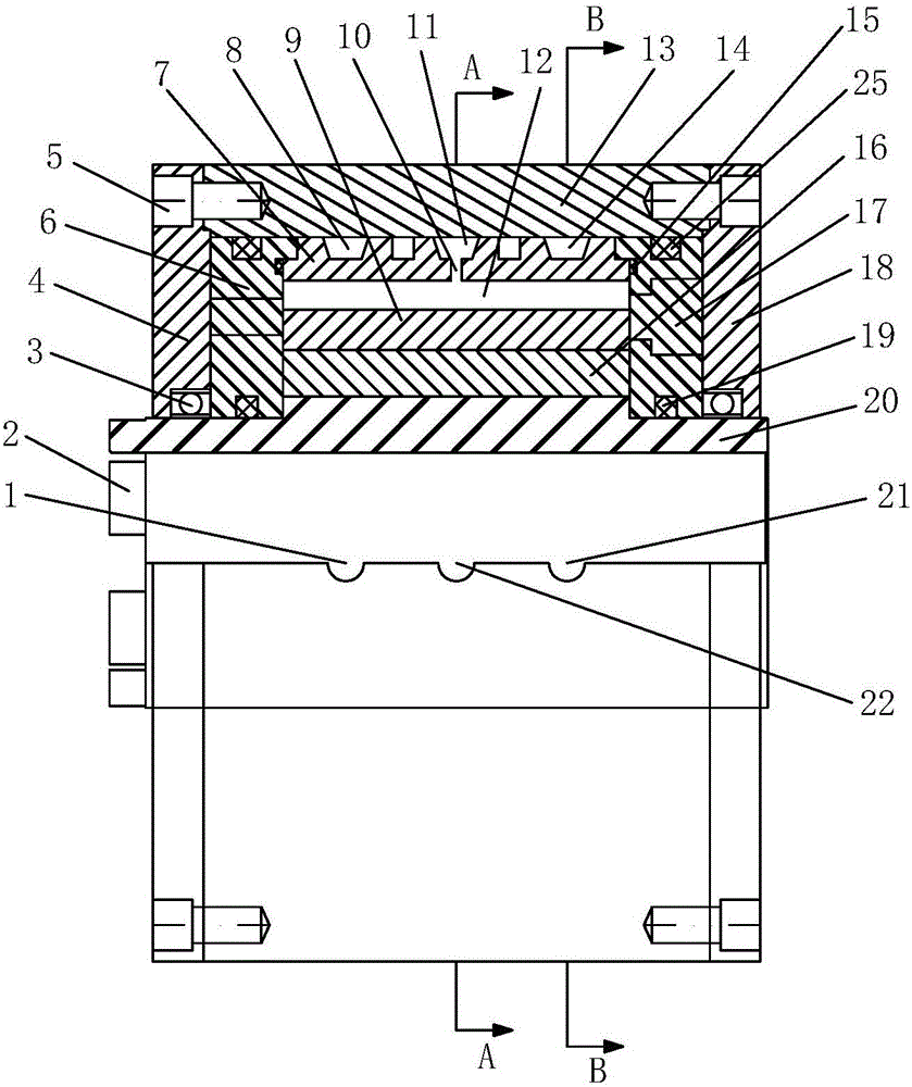
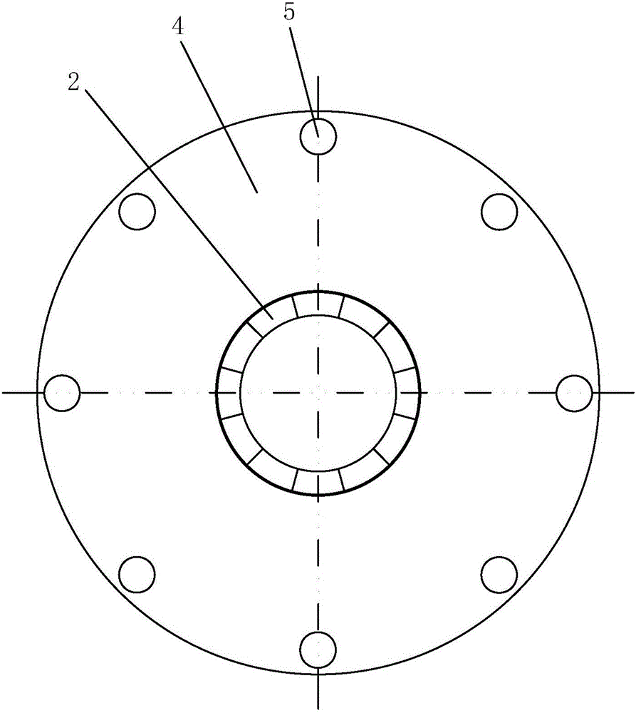
[0047] Such as Figure 1 to Figure 5 As shown, the present invention includes a shaft sleeve 20 and a concave cam rotor 16 fixedly installed on the shaft sleeve 20, a left stopper 6 and a right stopper 17 are rotatably installed on the shaft sleeve 20, and the left stopper 6 and the right stopper The stoppers 17 are located at the left and right ends of the concave cam rotor 16 respectively, a stator 7 is fixed between the left stopper 6 and the right stopper 17, and the stator 7 is sleeved outside the concave cam rotor 16, and the outside of the stator 7 A housing 13 is fixed, and the housing 13 is provided with a housing oil return interface 1, a blade oil inlet interface 22 and a housing oil inlet interface 21. The stator 7 is a hollow cylindrical structure, and an annular return port is provided on the outer wall of the stator 7. Oil groove 8, annular vane oil groove 11 and annular oil inlet groove 14, the inner wall of the stator 7 is provided with a plurality of vane oil...


PUM


Abstract

The invention discloses a cam rotor hydraulic motor for distributing oil in an abdominal cavity. The cam rotor hydraulic motor comprises a shaft sleeve, and a left stopper, a concave surface cam rotor and a right stopper mounted on the shaft sleeve in sequence from left to right; a stator is fixed between the left stopper and the right stopper, and sleeves the concave surface cam rotor; a shell is fixed outside the stator, and is provided with a shell oil return joint, a blade oil inlet joint and a shell oil inlet joint; an annular oil return groove, an annular blade oil groove and an annular oil inlet groove are formed in the outer wall of the stator; multiple blade oil ways and blade cavities are axially formed in the inner wall of the stator; radial blade oil inlet holes are formed in the stator; double blades are arranged in the blade cavities; and multiple pressureless cavity oil return holes and pressure cavity oil inlet holes are formed in the stator in the radial direction. The cam rotor hydraulic motor adopts a structure form of distributing the oil in the abdominal cavity, replaces a complex oil distribution disc mechanism by the annular oil grooves and the oil holes, is simpler in design and machining, preferably solves the sealing problem of hydraulic parts, and improves the efficiency.

Description

technical field [0001] The invention relates to a low-speed rotary hydraulic motor, in particular to a cam rotor hydraulic motor suitable for abdominal cavity oil distribution in drilling and blasting engineering construction such as tunnels and mines. Background technique [0002] At present, in hydraulic machines that require low-speed rotation, and at the same time set other components at the center of rotation or require simultaneous movement and other compound motions, the usual solution is to install another motion mechanism to complete it, which results in increased It reduces the size of the equipment and energy consumption, and sometimes it cannot be completed due to the limitation of the volume. The existing technology generally adopts the structural form of oil distribution plates at both ends. The design and processing of the oil distribution mechanism such as the oil distribution plate of the hydraulic motor with this structure are relatively complicated, and th...

Claims


Application Information

Patent Timeline
Patent Type & Authority Applications(China)
IPC IPC(8): F03C2/30
CPCF03C2/304
Inventor 王向军王亦民
Owner 王向军
Why Eureka
Try Eureka