
Combing mechanism for full-automatic underground parking lot and use method

An underground parking lot, fully automatic technology, which is applied to the buildings, building types, buildings and other directions where cars are parked. It can solve the problems of inability to correct the car position, high lubrication requirements, and high operating noise, so as to achieve convenient and fast maintenance and lubrication. The effect of low requirements and reduced failure rate

Inactive Publication Date: 2016-08-10
ANSHAN ZIZHU ENG EQUIP MFG
View PDF5 Cites 2 Cited by
  • Summary
  • Abstract
  • Description
  • Claims
  • Application Information

AI Technical Summary

Problems solved by technology

In the three-dimensional garage, the jig arm used to clamp the vehicle when accessing the vehicle is mostly driven by a chain, and the nut and screw are lifted. The transmission efficiency is low, the operation noise is large, the structure is cumbersome, and the failure rate is high.
[0005] In the prior art, the patent application number: 201410526035.6 discloses a single-shaft drive clamping wheel device for a mechanical garage, which performs clamping operation on the front and rear wheels of the car body to achieve the purpose of accessing the car, but both the front and rear wheels are operated by clamping wheels. For some front-drive vehicles, the rear wheels will be misaligned during the parking process, resulting in unstable access and cannot meet the requirements for correcting the car's position.
At the same time, this kind of device has high requirements for lubrication, and needs frequent maintenance in the underground humid environment, resulting in a high failure rate.

Method used


Image

  • Combing mechanism for full-automatic underground parking lot and use method
  • Combing mechanism for full-automatic underground parking lot and use method

Examples


Embodiment Construction

[0021] The present invention will be described in detail below in conjunction with the accompanying drawings, but it should be pointed out that the implementation of the present invention is not limited to the following embodiments.

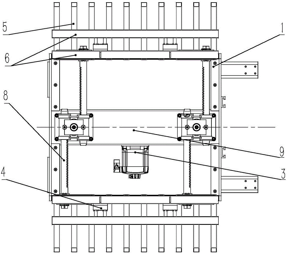
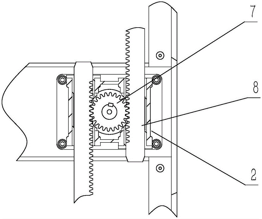
[0022] See figure 1 , figure 2 , a comb mechanism for a fully automatic underground parking lot, including a box body 1, a servo motor 3, a reducer 9, a gear 7, a rack 8, and a complete vehicle part 4, and the output end of the servo motor 3 passes through the reducer 9 and the gear 7 is connected, both sides of the gear 7 mesh with two racks 8, and the ends of the racks 8 are fixedly connected with the vehicle parts 4. There are two gears 7, and the rack 8 is connected with the end of the whole vehicle part 4. The gear 7 drives the rack 8 to move in translation in the guide seat 2. The speed reducer 9 can realize the purpose that a servo motor 3 drives two gears 7 to rotate at the same time.

[0023] The whole vehicle part 4 includes a comb...


PUM


Abstract

The invention relates to a combing mechanism for a full-automatic underground parking lot and a use method. The combing mechanism comprises a box, a servo motor, a speed reducer, gears, racks, an entire vehicle component and a guide base, wherein the output end of the servo motor is used for driving the gears to be connected through the speed reducer; both sides of the gears are meshed with two racks; the end parts of the racks are fixedly connected with the entire vehicle component; the gears are used for driving the racks to translate in the guide base. The combing mechanism has the advantages that the combining mechanism is fixed to a trolley conveying mechanism, and plays roles in carrying rear wheels of a vehicle and correcting a vehicle position. The overall structure is simple and compact, the lubricating requirement is low, the fault rate is lowered, stable performance of underground parking lot equipment is ensured, and the requirement of underground damp environment can be met. Automatic parking is realized, and the parking efficiency is increased. A non-standard reducing mechanism is adopted to fulfill the aim of driving two gears with one servo motor. The entire vehicle component is of a steel structure form, so that the vehicle position can be corrected, and force needed for correcting the vehicle is displayed.

Description

technical field [0001] The invention belongs to the field of automatic parking lots, and in particular relates to a comb mechanism and a use method of a fully automatic underground parking lot. Background technique [0002] At present, underground parking lots are mainly three-dimensional parking lots and traditional parking lots. Among them, the three-dimensional parking lot is a special equipment that is automatically sent to the underground space by using the parking equipment similar to the elevator. In comparison, the three-dimensional parking lot occupies a small space, has low input costs, and has a good future market and economic prospects. At the same time, the widespread use of three-dimensional parking systems has become an inevitable trend in the development of urban traffic automation, informatization, and networking. [0003] There are two types of existing mechanical three-dimensional garages, one is the displacement type, the entire load-carrying mechanism ...

Claims


Application Information

Patent Timeline
Patent Type & Authority Applications(China)
IPC IPC(8): E04H6/18
CPCE04H6/185
Inventor 曹维新
Owner ANSHAN ZIZHU ENG EQUIP MFG
Learn More