Cable pay-off rack

A technology for pay-off racks and cables, applied in the field of pay-off racks, can solve problems such as difficulty in determining the length of cables, and achieve the effects of saving effort, preventing dragging to the ground, and preventing collapse

Inactive Publication Date: 2016-08-10
ZHANGQIU POWER SUPPLY CO OF STATE GRID SHANDONG ELECTRIC POWER CO +1
View PDF7 Cites 10 Cited by
  • Summary
  • Abstract
  • Description
  • Claims
  • Application Information

AI Technical Summary

Problems solved by technology

[0003] The technical problem to be solved by the present invention is to provide a cable pay-off stand, which solves the problem of difficulty in determining the length of the cable line and preventing the cable from dragging the floor

Method used


Image

  • Cable pay-off rack
  • Cable pay-off rack
  • Cable pay-off rack

Examples


Embodiment Construction

[0022] In order to clearly illustrate the technical features of the solution, the solution will be described below through a specific implementation mode combined with the accompanying drawings.

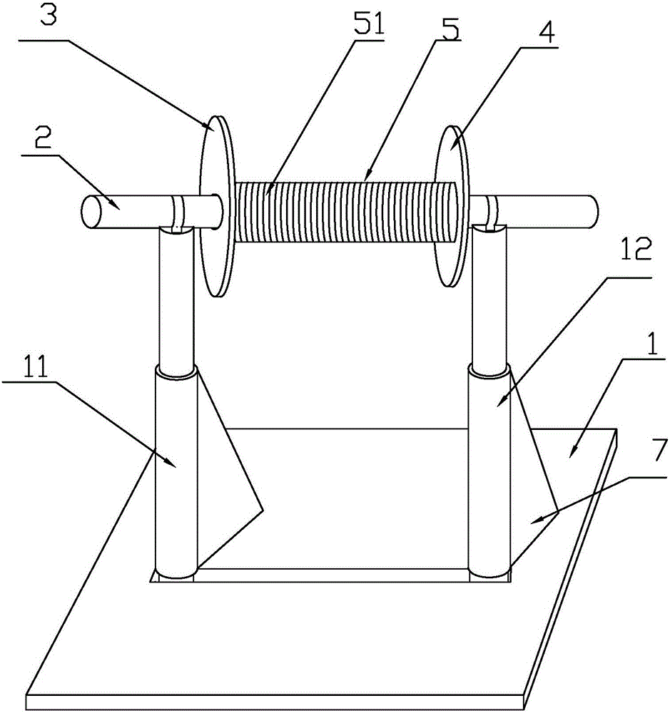
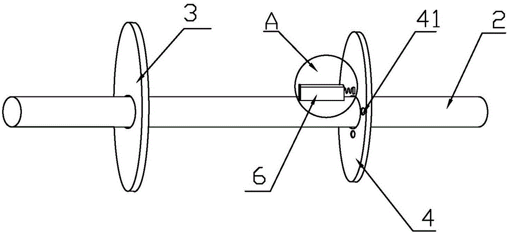
[0023] Such as Figure 1-5 As shown, a cable pay-off frame includes a base and a pay-off device, the base is used to support the pay-off device, the base includes a bottom plate 1, a first air pressure telescopic rod 11 and a second air pressure telescopic rod 12, The first air pressure expansion rod 11 and the second air pressure expansion rod 12 are vertically and symmetrically distributed at both ends of the central axis of the bottom plate 1. When in use, the bottom plate is placed on the ground, and the bottom plate has a supporting effect on the upper pay-off device. The first air pressure telescopic rod and the second air pressure telescopic rod have a telescopic effect. When in use, the first air pressure telescopic rod and the second air pressure telescopic rod can adjust th...


PUM


Abstract

The invention provides a cable pay-off rack. The cable pay-off rack comprises a base and a pay-off device. The base is used for supporting the pay-off device and comprises a bottom plate, a first pneumatic telescopic rod and a second pneumatic telescopic rod. The first pneumatic telescopic rod and a second pneumatic telescopic rod are vertically and symmetrically distributed at the two ends of the central axis of the bottom plate. The pay-off device comprises a first rotating plate, a second rotating plate and a fixing shaft, wherein the fixing shaft is connected with a rotating shaft of the first rotating plate and the second rotating plate and penetrates through the rotating shaft. The first rotating plate and the second rotating plate are fixedly connected to the two ends of the rotating shaft correspondingly. The rotating shaft rotates on the fixing shaft. The fixing shaft is provided with a positioning device. The second rotating plate is provided with a plurality of positioning holes used cooperatively with the positioning device. The cable pay-off rack has the characteristics of being reasonable in structure design, convenient to use and wide in application scope.

Description

technical field [0001] The invention relates to a pay-off rack, in particular to a cable pay-off rack. Background technique [0002] As people's demand for electricity continues to increase, the speed of power construction is also accelerating. Cables are used more and more as common power transmission in electric power. At present, insulated wires, communication cables, power cables, etc. are mostly used in the market. In maintenance and construction sites, the use of these cables usually uses equipment with a relatively single structure and function, and the pay-off rack equipment is usually large, which cannot satisfy people's use of some cables with small diameters, which results in the installation of cables. At the work site, it is often necessary for multiple people to drag the cable to prevent the cable from being dragged to the ground, but it is also easy to bend the released line, which will affect subsequent use. In the process of dragging the electric wire, the ...

Claims


Application Information

Patent Timeline
Patent Type & Authority Applications(China)
IPC IPC(8): B65H49/32B65H49/18B65H61/00
CPCB65H49/18B65H49/324B65H61/00B65H2701/34
Inventor 李悦军高波程贯兵时卫东王化明张延芳孙茂森高向
Owner ZHANGQIU POWER SUPPLY CO OF STATE GRID SHANDONG ELECTRIC POWER CO
Why Eureka
Try Eureka