
Synchronous control method of two independent motor-driven steel conveyor chains

A synchronous control and independent motor technology, applied in the direction of conveyor control devices, conveyors, conveyor objects, etc., can solve the problems of sudden speed drop, fluctuation, load impact of the conveyor chain, etc., and achieve good results

Active Publication Date: 2019-02-19
MAANSHAN IRON & STEEL CO LTD
View PDF6 Cites 0 Cited by
  • Summary
  • Abstract
  • Description
  • Claims
  • Application Information

AI Technical Summary

Problems solved by technology

In actual use, there are two defects in this two-stage steel conveyor chain synchronous control method: first, when the driven steel conveyor chain is overloaded for a short time, the speed of the driven steel conveyor chain drops sharply due to a sudden increase in load, This will inevitably lead to asynchrony between the driven steel conveyor chain and the active steel conveyor chain, which will cause the steel to be skewed on the conveyor chain; second, the position control of the master-slave steel conveyor chain requires a special position controller (such as Siemens D425 Motion controller, etc.), in view of the relatively bad operating conditions of the steel stacking bed conveyor chain, the load impact and fluctuations of the conveyor chain are often caused by the blockage of the steel end position, and the conveyor chain position controller often sends out fault information. Causes the inverter of the conveyor chain drive to trip

Method used


Image

  • Synchronous control method of two independent motor-driven steel conveyor chains
  • Synchronous control method of two independent motor-driven steel conveyor chains

Examples


Embodiment Construction

[0018] Referring to the accompanying drawings, through the description of the embodiments, the specific embodiments of the present invention include the shape, structure, mutual position and connection relationship of each part, the function and working principle of each part, and the manufacturing process of the various components involved. And the method of operation and use, etc., are described in further detail to help those skilled in the art have a more complete, accurate and in-depth understanding of the inventive concepts and technical solutions of the present invention.

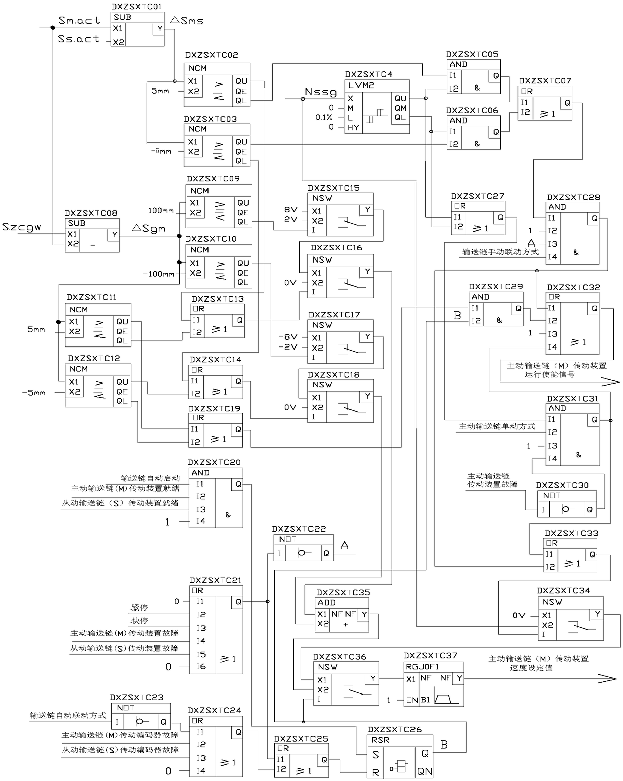
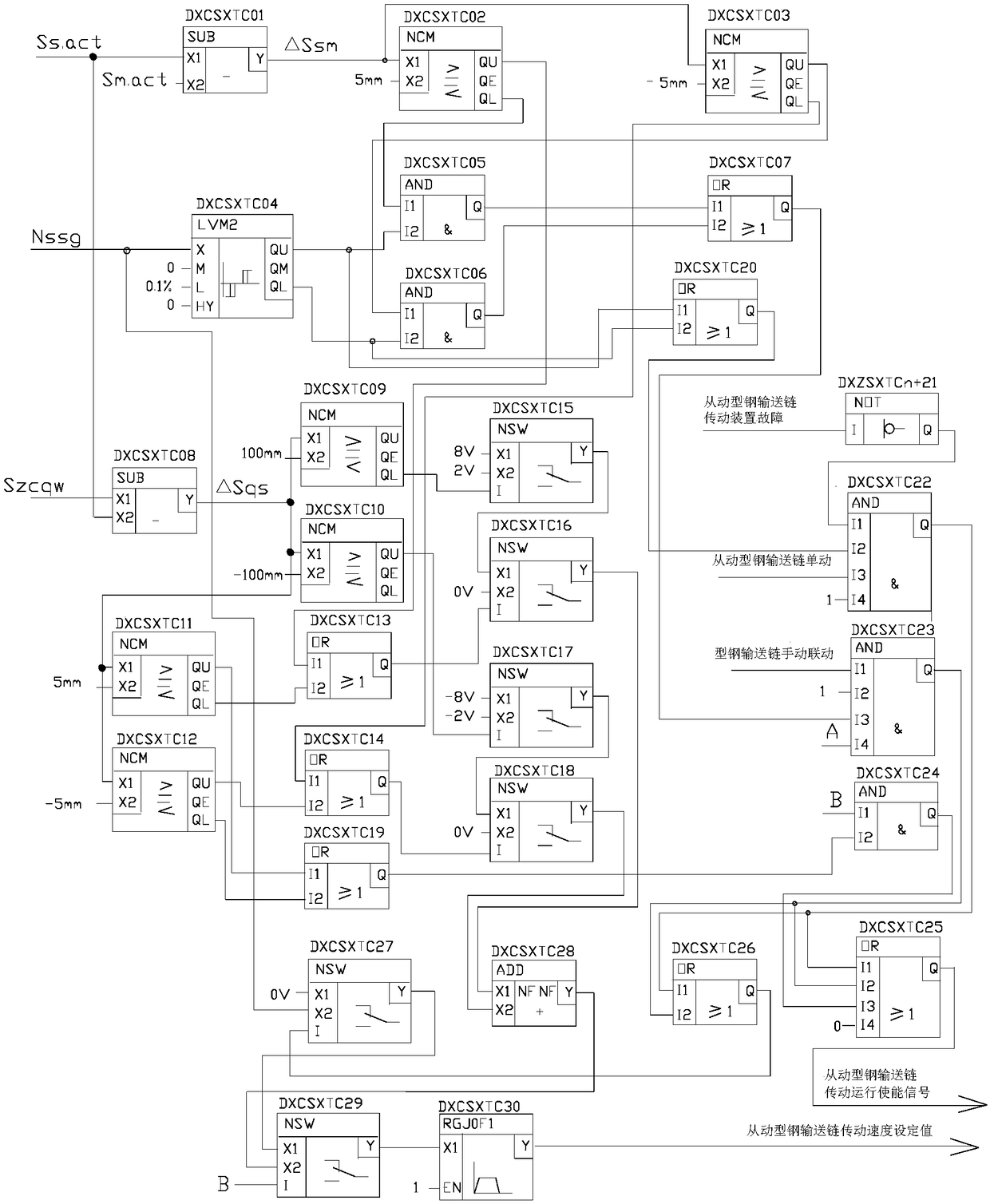
[0019] For the synchronization of two sections of steel conveyor chains driven by independent DC (or variable frequency) motors, the present invention adopts a master-slave control mode to realize the synchronous control between the two sections of steel conveyor chains, that is, one of the two sections of steel conveyor chains is selected as the active section of steel conveyors. chain, and the other...


PUM


Abstract

The invention discloses a synchronous control method for two independent motor drive type steel conveying chains. The method comprises driving type steel conveying chain synchronous control and driven type steel conveying chain synchronous control, according to the driving type steel conveying chain synchronous control and the driven type steel conveying chain synchronous control, retreating terminal position values of a main conveying chain and a slave conveying chain are 0 mm, and given position values and actual position values of the main conveying chain and the slave conveying chain are positive values or zero. The driving type steel conveying chain synchronous control comprises a driving type steel conveying chain synchronous position over-tolerance judging unit, a driving type steel conveying chain automatic linkage transmission enabling control unit, a driving type steel conveying chain automatic linkage speed given control unit, a driving type steel conveying chain manual linkage transmission enabling and speed given control unit and a driving type steel conveying chain single-action transmission enabling and speed given control unit. The control method is used in two-section conveying chains of a large H-shaped steel CP9 stacking machine tool of the Maanshan Iron and Steel Company, and has good effect.

Description

technical field [0001] The invention belongs to the technical field of hydraulic transmission control, and in particular relates to a synchronous control method for two independent motor-driven steel conveyor chains. Background technique [0002] In industrial production, it is common for two independent motor-driven equipment to operate synchronously, and the two-section conveyor chain of the large H-shaped steel stacking bed of Masteel is one of them. In order to realize the synchronization of the two conveyor chains of the stacking bed, the conveyor chain control system adopts a conventional electrical synchronous control method, that is, each conveyor chain is driven by a motor, and each motor is equipped with an encoder for speed and position detection, and The transmission motor of each section of the conveyor chain adopts a three-closed-loop control method with independent current inner loop, speed and position outer loop. In order to realize the synchronous control ...

Claims


Application Information

Patent Timeline
Patent Type & Authority Patents(China)
IPC IPC(8): B65G43/10H02P5/56
CPCB65G43/10B65G2203/0291
Inventor 叶光平汪志远吴卫华徐洪苏炜朱旭光
Owner MAANSHAN IRON & STEEL CO LTD
Learn More