Eureka AIR delivers breakthrough ideas for toughest innovation challenges, trusted by R&D personnel around the world.

A laser optical path correction device and method for CO2 laser cutting and engraving machine

A laser cutting and calibration device technology, which is applied in the field of laser calibration, can solve problems such as difficult calibration and easy deviation of calibration laser tubes, and achieve the effects of avoiding unsafe factors, safe adjustment, and convenient realization

Inactive Publication Date: 2018-06-08
WUHAN INSTITUTE OF TECHNOLOGY
View PDF5 Cites 0 Cited by
  • Summary
  • Abstract
  • Description
  • Claims
  • Application Information

AI Technical Summary

Problems solved by technology

[0005] The technical problem to be solved by the present invention is to provide a CO2 laser cutting and engraving device that can accurately correct the laser light path and is easy to use and safe for the defects in the prior art that are prone to offset and difficult to correct when correcting the laser tube. On-board laser optical path correction device and method

Method used


Image

  • A laser optical path correction device and method for CO2 laser cutting and engraving machine
  • A laser optical path correction device and method for CO2 laser cutting and engraving machine
  • A laser optical path correction device and method for CO2 laser cutting and engraving machine

Examples


Embodiment Construction

[0025] In order to make the object, technical solution and advantages of the present invention clearer, the present invention will be further described in detail below in conjunction with the accompanying drawings and embodiments. It should be understood that the specific embodiments described here are only used to explain the present invention, not to limit the present invention.

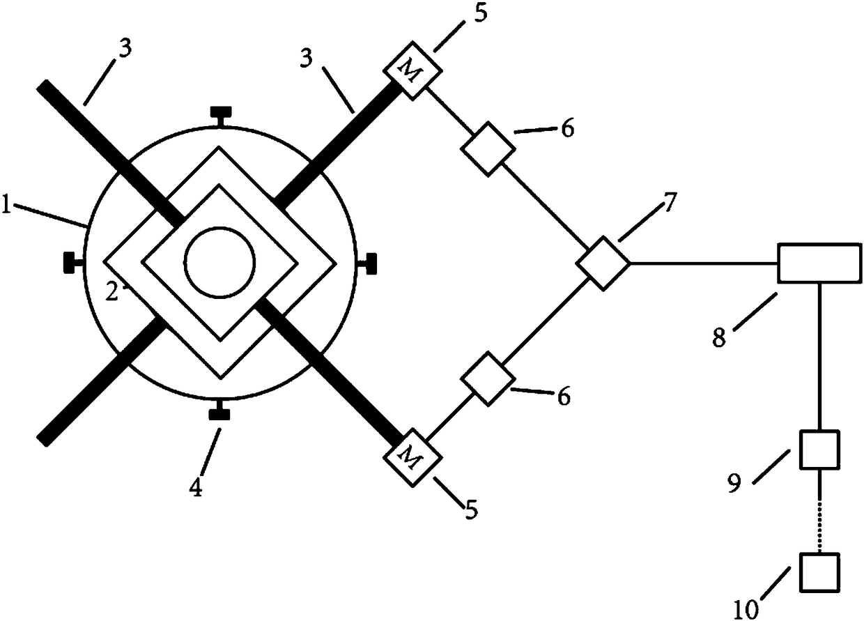
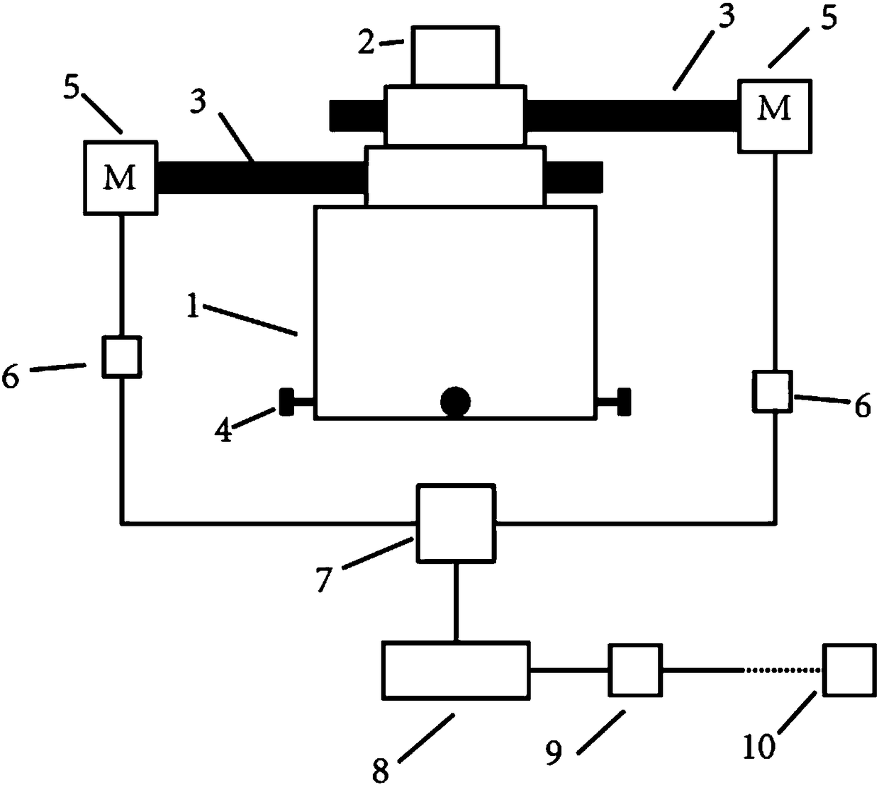
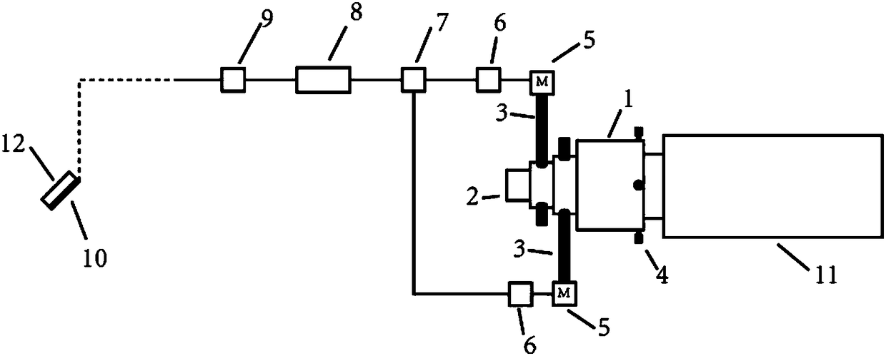
[0026] Such as figure 1 As shown, the embodiment of the present invention is used for CO 2 The laser optical path correction device on the laser cutting and engraving machine includes a laser transmitter 2, the device also includes a connector 1 and an adjustment shaft 3, and the connector 1 and the CO 2 The laser tube 11 is fixedly connected, and the adjustment shaft 3 is installed on the connector 1; the laser reflection head 2 is connected to the adjustment shaft 3, and the laser reflection head 2 moves under the drive of the adjustment shaft 3;

[0027] The device also includes a central proc...


PUM


Abstract

The invention discloses a laser optical path correcting device and a method for a CO2 laser cutting carver. The device comprises a laser emitting head, and further comprises a connector and an adjusting shaft; the connector is fixedly connected with a CO2 laser tube; the adjusting shaft is mounted on the connector; and a laser reflecting head is connected with the adjusting shaft, and is driven by the adjusting shaft to move. The device further comprises a central processing unit, a positioning module and a sensor; the sensor is used for recording a laser position on a reflecting mirror and converting the laser position to an electric signal; the positioning module converts an electric signal acquired by the sensor to an analog quantity to transmit to the central processing unit; and the central processing unit processes the analog quantity to control movement of the adjusting shaft so as to drive the laser emitting head to move. The device can quickly and accurately adjust a laser optical path, improves the working precision and safety of the CO2 laser cutting carver, realizes automation of the visual light adjusting process, is wide in application, and can be applied to all CO2 laser equipment.

Description

technical field [0001] The invention relates to the field of laser correction, in particular to a laser light path correction device and method for a CO2 laser cutting and engraving machine. Background technique [0002] CO 2 Laser cutting and engraving machines are extremely versatile in the processing of materials. CO 2 Laser cutting and engraving machine, which can cut, engrave and mark materials, is widely used in electronic components, integrated circuits (IC), electrical appliances, mobile communications, hardware products, tool accessories, precision instruments, glasses clocks, jewelry, Auto parts, plastic buttons, building materials, PVC pipes. CO 2 Laser cutting and engraving machine has the advantages of high processing precision, fast speed, smooth incision, convenient use, low cost, environmental protection and safety. [0003] in CO 2 During the use of laser cutting and engraving machines, it is often necessary to correct the laser light path. For exampl...

Claims


Application Information

Patent Timeline
Patent Type & Authority Patents(China)
IPC IPC(8): B23K26/046B23K26/362
CPCB23K26/046B23K26/361
Inventor 赵培苏轼王莹
Owner WUHAN INSTITUTE OF TECHNOLOGY
Why Eureka
Eureka Blog
Learn More