
A positioning-guided orthopedic reduction forceps

A technology of positioning guide and reset forceps, which is applied in fixers, medical science, surgical forceps, etc., can solve the problems of loss of accurate guidance, large surgical trauma, prolonged operation time, etc., achieve reliable clamping and precise guidance, reduce incision and Trauma, the effect of reducing the chance of infection

Active Publication Date: 2018-08-21
段强民
View PDF1 Cites 0 Cited by
  • Summary
  • Abstract
  • Description
  • Claims
  • Application Information

AI Technical Summary

Problems solved by technology

[0002] In the treatment of humeral intercondylar fractures, humeral supracondylar fractures, humeral medial condyle fractures, and lateral condyle fractures, the ulnar nerve travels in the ulnar nerve groove on the posterior side of the medial epicondyle and the radial nerve is close to the bone surface at the crest of the lateral epicondyle of the humerus The reason for this is that the traditional approach in performing medial and lateral needle fixation is the conventional combined medial and lateral approach, fracture reduction under direct vision, blind needle puncture, and then fluoroscopy to confirm whether the entry and exit points of the drill bit and the length of the opposite side are ideal. When threading the needle, because a point cannot determine a straight line, the drill bit cannot accurately reach the ideal drilling point that can avoid important tissue damage after drilling from the entry point
If it is not ideal, multiple adjustments are required, resulting in prolonged operation time, large surgical trauma, increased patient pain and recovery time, and a higher risk of iatrogenic damage to important blood vessels and nerves during blind puncture
[0003] Most of the existing orthopedic reduction forceps only have the function of reduction, that is, the reduction and fixation of the bone at the fracture site, and cannot guide drilling
In the orthopedic guiding reduction forceps disclosed in Chinese invention patent 201310604750.5, although it is also possible to carry out guided drilling after performing bone reduction, in this patent, there are the following deficiencies: 1. Both clamping ends of this patent are Needle-point shape is used, and the two clamping ends are not in a straight line with the channel of the sleeve. If the two clamping tips are used to clamp and reset and guide drilling through the sleeve, at this time, if the pliers body rotates to cause the needle tip to rotate, the sleeve will It will make an arc-shaped rotation with the tip of the pliers as the center of the circle, which will cause a large swing at the drilling point of the channel of the guide sleeve, which will cause the deviation of the drilling point, resulting in the deviation of the position of the internal fixation, and the loss of accurate guidance. function, which is a serious shortcoming
At the same time, the position deviation is also likely to cause accidental injury to the surrounding important tissues.
2. In this patent, the pliers tips are all in the shape of tines. When the rotating drill bit reaches the tines, collision between the drill bit and the tines is likely to occur, which may cause wear or breakage of the drill bit or (and) tines.
3. In this patent, the drill bit has no guiding and restricting effect after drilling out of the bone, and it is easy to accidentally injure the surrounding important tissues, resulting in iatrogenic loss, and severe sequelae

Method used


Image

  • A positioning-guided orthopedic reduction forceps
  • A positioning-guided orthopedic reduction forceps
  • A positioning-guided orthopedic reduction forceps

Examples


Embodiment 1

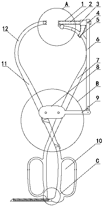
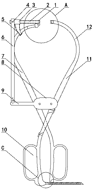
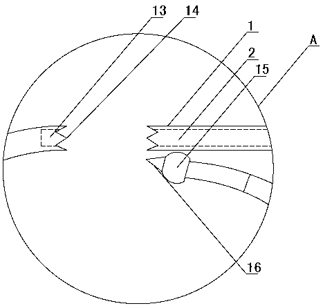
[0032] Such as Figure 1~2 As shown, a positioning-guided orthopedic reduction forceps includes a left forceps arm 11 and a right forceps arm 7. The left forceps arm 11 and the right forceps arm 7 are arranged alternately and can be fixed by a fixed stopper 8. The left forceps arm 11 The intersection point with the right tong arm 7 is located at the bottom of the fixed limiter 8 . At the lower ends of the left tong arm 11 and the right tong arm 7, respectively, a left and right corresponding finger cuffs 10 are arranged, which is convenient for the surgeon to carry out the clamping operation. The upper ends of the left tong arm 11 and the right tong arm 7 are respectively provided with a first clamping tip and a second clamping tip through an arc-shaped connecting section 12, and the first clamping tip and the second clamping tip are arranged opposite to each other left and right. The arc-shaped connection section 12 connected to the upper ends of the left pincer arm 11 and t...

Embodiment 2

[0049] Such as Figure 7 As shown, the difference between embodiment 2 and embodiment 1 is: in embodiment 2, the end of the first clamping tip maintains the cone tip guide end, and the end of the second clamping tip cancels the cone tip guide end, which is designed as The inclined surface 32 with only one tip forms a tapered sleeve with only one tip, and the other designs are the same as in Embodiment 1. In this embodiment, the end of the guide sleeve 1 can also be designed as an inclined surface 32 with only one tip, and the design of the tapered guide end remains at the end of the second clamping tip.

Embodiment 3

[0051] Such as Figure 8 As shown, the difference between embodiment 3 and embodiment 1 is that in embodiment 3, the design of the conical point guide end of multiple tips is canceled at the end of the right clamp arm 7, and the design is the same inclination as the second clamping tip surface 32, and a guide groove 13 matching with the channel 2 is provided at the center of the inclined surface 32.

[0052] In this positioning-guided orthopedic reduction forceps, the arrangement of the first clamping tip and the second clamping tip can be any combination of the above embodiments.


PUM


Abstract

A positioning-guided orthopedic reduction forceps belongs to the field of orthopedic medical devices. Consists of two pliers arms, characterized in that a first clamping tip is provided on the upper end of one pliers arm, a guide sleeve (1) is provided on the upper end of the other pliers arm, and a guide sleeve (1) is provided at the end of the guide sleeve (1). The second clamping tip, the first clamping tip is opposite to the second clamping tip. In this positioning-guided orthopedic reduction forceps, the first clamping tip and the second clamping tip arranged opposite to each other can realize reliable clamping and precise guidance of the fracture fragment, which is conducive to the accurate drilling of the drill into the bone , Contribute to the successful completion of the operation. Due to the more accurate positioning and guidance during the operation, the incidence of trauma and wound infection can be reduced as much as possible during the operation, which is conducive to postoperative wound healing and joint function recovery. At the same time, due to the small incision and trauma, it is minimally invasive. Surgery, with aesthetic curative effect.

Description

technical field [0001] A positioning-guided orthopedic reduction forceps belongs to the field of orthopedic medical devices. Background technique [0002] In the treatment of humeral intercondylar fractures, humeral supracondylar fractures, humeral medial condyle fractures, and lateral condyle fractures, the ulnar nerve travels in the ulnar nerve groove on the posterior side of the medial epicondyle and the radial nerve is close to the bone surface at the crest of the lateral epicondyle of the humerus The reason for this is that the traditional approach in performing medial and lateral needle fixation is the conventional combined medial and lateral approach, fracture reduction under direct vision, blind needle puncture, and then fluoroscopy to confirm whether the entry and exit points of the drill bit and the length of the opposite side are ideal. When threading the needle, because a point cannot determine a straight line, the drill bit cannot accurately reach the ideal dril...

Claims


Application Information

Patent Timeline
Patent Type & Authority Patents(China)
IPC IPC(8): A61B17/90A61B17/88A61B17/28
CPCA61B17/2812A61B17/8866A61B17/90
Inventor 段强民
Owner 段强民
Learn More