
Design and manufacture of multi-mode optical fibers

A technology of multimode optical fiber and optical fiber, applied in cladding optical fiber, graded index core/cladding optical fiber, optics, etc.

Active Publication Date: 2016-08-03
OFS FITEL LLC
View PDF7 Cites 12 Cited by
  • Summary
  • Abstract
  • Description
  • Claims
  • Application Information

AI Technical Summary

Problems solved by technology

Such a process may be too restrictive to achieve the desired efficient CWDM-optimized MMF while addressing processing / manufacturing issues

Method used


Image

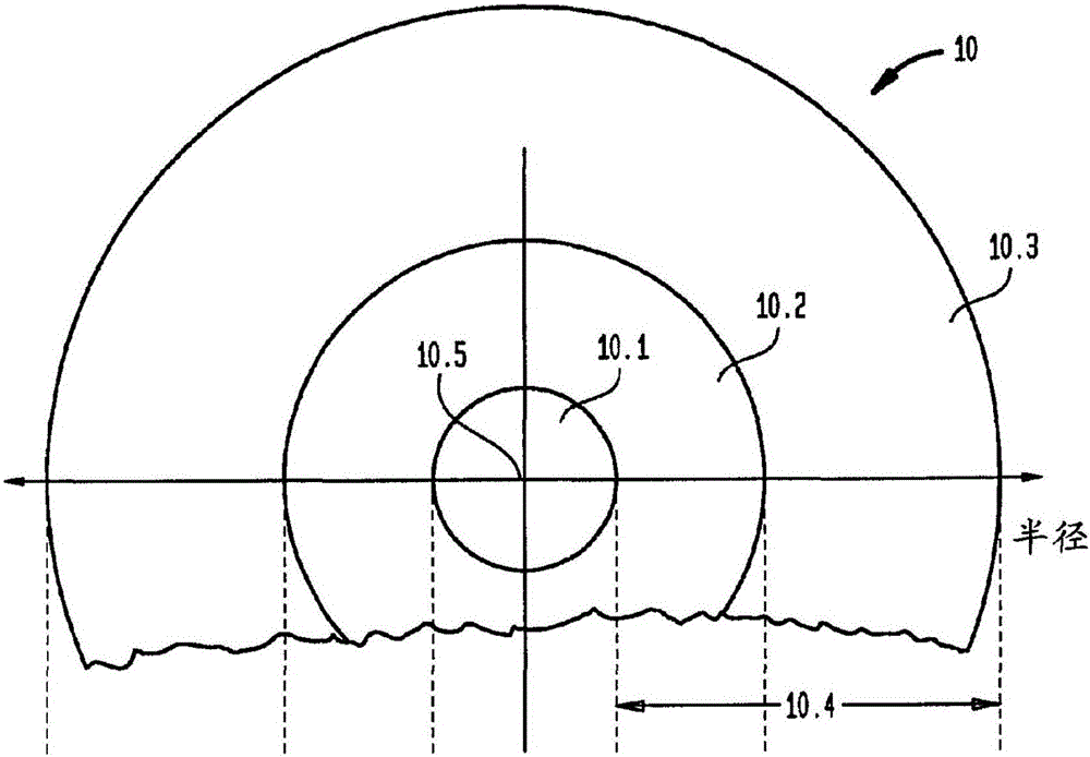
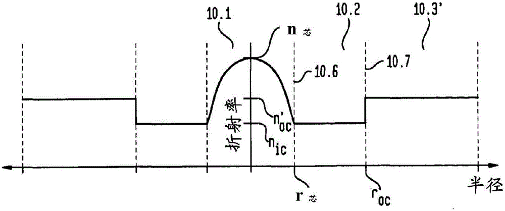
  • Design and manufacture of multi-mode optical fibers
  • Design and manufacture of multi-mode optical fibers
  • Design and manufacture of multi-mode optical fibers

Examples


Embodiment Construction

[0045] Glossary

[0046] Bending: Macrobending (often referred to simply as bending) occurs when an optical fiber is bent, coiled, or crimped such that its curvature is relatively constant along at least a portion of its length. In contrast, microbending occurs when the curvature changes significantly over an adiabatic length scale for a particular fiber (eg, along the length of the fiber on sub-millimeter scales). Such microbends are formed, for example, by pressing the fiber against sandpaper in a standard microbend test.

[0047] Intermediate Wavelength: References to wavelengths in this discussion are intended to refer to wavelengths representing the intermediate wavelengths of particular light emissions, with the understanding that all such emissions are characterized by known ranges including wavelengths above and below the intermediate wavelength line width.

[0048] Glass Fiber: The type of fiber described here is essentially made of glass (e.g., silica) in which the...


PUM


Abstract

Described is a technique for the design and manufacture of MMFs. Designs are implemented so as to limit the maximum variation in z{r, Lambda) with respect to wavelength, where z(r. Lambda) is the dielectric constant weighted by the square of the vvaveiengih. MMFs for use in CWDM applications are specifically described.

Description

[0001] Cross References to Related Applications [0002] This application claims priority to Provisional Application Serial No. 61 / 934223, filed January 31, 2014, and entitled "CWDM-optimizedMMF." technical field [0003] The present invention relates to multimode fibers (MMF) and more particularly to the design and manufacture of such fibers optimized for sparse wavelength division multiplexing (CWDM) applications. Background technique [0004] As discussed by Fleming et al. in U.S. Patent No. 7,421,174 (2008), which is incorporated herein by reference, early investigators of MMF design recognized that a parabolic index profile in the core significantly reduces the mode Dispersion between. However, they assumed that the parabolic profile should be optimized and should be the same for all transmission wavelengths and fiber compositions. This approach does not take into account the variation in refractive index dispersion in the different material compositions from which th...

Claims


Application Information

Patent Timeline
Patent Type & Authority Applications(China)
IPC IPC(8): G02B6/02G02B6/028
CPCG02B6/03627G02B6/03633G02B6/03694G02B6/0288G02B27/0012
Inventor K·巴尔玛蒂J·W·弗莱明金真基R·L·灵戈R·舒伯金D·维德雅M·F·彦
Owner OFS FITEL LLC
Learn More