Camera and Endoscope Devices

A technology of an imaging device and imaging element, which is applied to endoscopes, telescopes, image communications, etc., can solve the problems of increasing the number of optical components and failing to achieve thinning, and achieve the effect of reducing the diameter and reducing the size.

Active Publication Date: 2018-06-26
OLYMPUS CORP
View PDF8 Cites 0 Cited by
  • Summary
  • Abstract
  • Description
  • Claims
  • Application Information

AI Technical Summary

Problems solved by technology

[0012] In addition, in the technique of Patent Document 3, there is also a problem that since a glass cover with a large outer diameter is used to secure a space for connecting the imaging element and the flexible substrate, sufficient reduction in diameter cannot be achieved, and the The use of optical components for fitting with the lens frame and securing space for the connection of the imaging element and the flexible substrate increases the length of the hard part at the tip of the optical component.

Method used


Image

  • Camera and Endoscope Devices
  • Camera and Endoscope Devices
  • Camera and Endoscope Devices

Examples


Embodiment Construction

[0046] In the following description, an endoscope apparatus having a camera module will be described as a mode for carrying out the present invention (hereinafter referred to as “embodiment”). Also, the present invention is not limited to this embodiment. In addition, in description of drawings, the same code|symbol is attached|subjected to the same part. In addition, it should be noted that the drawings are schematic, and the relationship between the thickness and width of each member, the ratio of each member, and the like are different from actual ones. In addition, parts from which dimensions or ratios differ between drawings are also included.

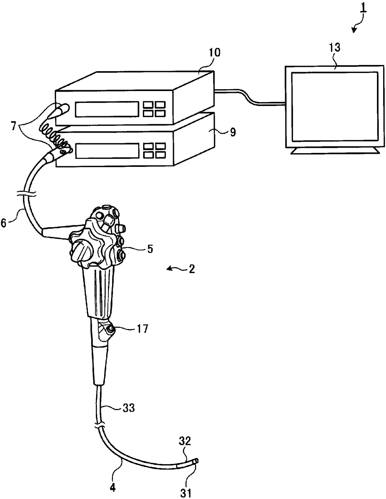
[0047] figure 1 It is a diagram schematically showing the overall configuration of an endoscope system according to an embodiment of the present invention. Such as figure 1 As shown, the endoscope device 1 has an endoscope 2 , a universal cable 6 , a connector 7 , a light source device 9 , a processor (control device) 10 , and...


PUM


Abstract

To provide an imaging device and an endoscope device capable of miniaturization. The imaging device (35) of the present invention is characterized in that it has: an optical component holder (36), which is formed in a hollow shape with both ends open, and has a notch (36c) on the side of one end; an objective lens (43), which is assembled In the inside of the optical component support (36), the light incident from the other end of the optical component support (36) is converged; the prism (37), which is assembled in the inside of the optical component support (36), makes the objective lens (43) The converging light reflection; the imaging element (38), which generates an electric signal by accepting the light reflected by the prism (37) and performing photoelectric conversion; and the substrate (39), which is electrically connected with the imaging element (38), and the prism ( 37) at least a part of the outer peripheral surface is formed as a cylindrical surface, the prism (37) is in contact with the inside of the optical component holder (36) with the cylindrical surface, and at least a part of the imaging element (38) is installed on the Side of the Optics Holder (36).

Description

technical field [0001] The present invention relates to an imaging device and an endoscope device that are installed at the tip of an insertion portion of an endoscope inserted into a subject to image the subject. Background technique [0002] Conventionally, endoscope apparatuses have been widely used for various inspections in the medical and industrial fields. Among them, in a medical endoscope apparatus, by inserting a flexible and slender insertion portion having an imaging device built in at a distal end portion into a body cavity of a subject such as a patient, observation of a subject site can be performed, Furthermore, the treatment tool can be protruded from the front end of the insertion part to perform treatment as needed, so it is widely used. [0003] In recent years, due to the expansion of the light-receiving area and the increase in the size of the imaging element due to the mounting of the processing circuit, the following imaging module has been proposed ...

Claims


Application Information

Patent Timeline
Patent Type & Authority Patents(China)
IPC IPC(8): A61B1/00A61B1/04
CPCA61B1/00096A61B1/05G02B23/2469G02B23/243G02B23/2484H04N23/555H04N23/55H04N23/54A61B1/051A61B1/00097
Inventor 佐竹七生
Owner OLYMPUS CORP
Why Eureka
Try Eureka