Gas insulation switching device

A technology of gas insulated switches and circuit breakers, which is applied in the direction of switchgear, switchgear setting, gas insulated substation, etc., which can solve the problems of increased manufacturing cost and longer wiring path, and achieve shortened length, reduced installation space, and realization of The effect of thinning

Inactive Publication Date: 2014-04-09
MITSUBISHI ELECTRIC CORP
View PDF8 Cites 0 Cited by
  • Summary
  • Abstract
  • Description
  • Claims
  • Application Information

AI Technical Summary

Problems solved by technology

Therefore, there is a problem that, in addition to the cost of plugging the board, the manufacturing cost of the conductor increases because the routing path of the conductor becomes long

Method used


Image

  • Gas insulation switching device
  • Gas insulation switching device
  • Gas insulation switching device

Examples


Embodiment approach 1

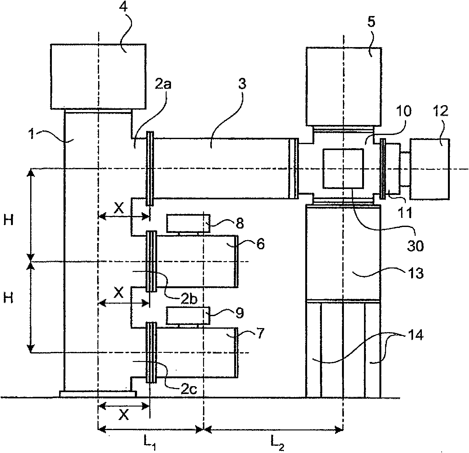
[0050] figure 1 It is a cross-sectional view showing the structure of the gas insulated switchgear according to the present embodiment, and is a view showing a unit for power transmission and reception lines. figure 2 It is a figure which shows the unit for transformer wires which is another form of the unit for power transmission and reception wires in this embodiment. in addition, image 3 It is a cross-sectional view showing the structure of the gas insulated switchgear according to the present embodiment, and is a view showing a unit for bus-bar connecting wires.

[0051] Such as figure 1 As shown, a circuit breaker 1 having a circuit breaker is installed inside a cylindrical container filled with an insulating gas. The circuit breaker 1 is a circuit breaker in which the central axis direction of the container is vertically perpendicular to the installation surface. An operating device 4 for operating the circuit breaker 1 is arranged on the upper part of the container...

Embodiment approach 2

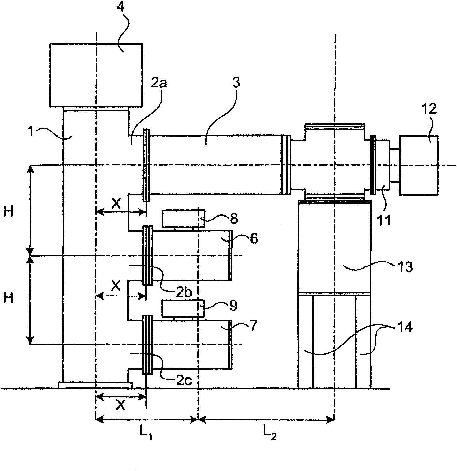
[0082] In Embodiment 1, the case of the multi-bus system was described, but in this embodiment, the case of the single-bus system will be described. Figure 7 It is a cross-sectional view showing the structure of the gas insulated switchgear according to the present embodiment, and is a view showing a unit for power transmission and reception lines. Figure 8 It is a figure which shows the unit for transformer wires which is another form of the unit for power transmission and reception wires in this embodiment.

[0083] Such as Figure 7 As shown, a circuit breaker 31 having a disconnection portion is provided inside a cylindrical container filled with an insulating gas. The circuit breaker 31 is a circuit breaker whose central axis direction of the container is vertically perpendicular to the installation surface. The circuit breaker 31 is disposed on the supporting frame 45 . In addition, on the upper part of the container of the circuit breaker 31, an operating device 34 ...


PUM


Abstract

In a multi-busbar system gas insulated switchgear, a power transmission / reception line unit (I) is constituted by providing a plurality of branch lead-out ports at regular intervals (interval H) along a vertical direction on the lateral side of a tank of a vertical-type circuit breaker, connecting a line-side device to the uppermost branch lead-out port, connecting the busbar-side devices to the lower branch lead-out ports, and arranging the line-side device to face the circuit breaker while placing multiple busbars therebetween. In a busbar link line unit (III), the tank length of a vertical-type circuit breaker is shorter than the tank length of the circuit breaker by the interval H, and an interval between a plurality of branch lead-out ports for busbar-side-device connection that are provided on the later side of the tank of the circuit breaker along a vertical direction is also the interval H.

Description

technical field [0001] The present invention relates to a gas insulated switchgear including a circuit breaker provided with a plurality of branch outlets on the side of a circuit breaker container. Background technique [0002] Gas insulated switchgear used in substations, power plants, etc., has various types of units corresponding to usage methods such as power transmission and reception wires, transformer wires, bus connection wires, and bus partition wires. Therefore, rather than designing and manufacturing these units separately, it is better to standardize the common parts to achieve common use. [0003] Patent Document 1 discloses a double-bus-type insulating switchgear. The above-mentioned double-bus-type gas-insulated switchgear is provided with three branch outlets on the side of the longitudinal circuit breaker container. The equipment connected to the outlet can be used for both power transmission and reception wires and bus connection wires. In the structure ...

Claims


Application Information

Patent Timeline
Patent Type & Authority Patents(China)
IPC IPC(8): H02B13/02
CPCH02B5/06H02B1/22H02B13/0358H02B13/045
Inventor 藤田大辅大塚卓弥贞国仁志
Owner MITSUBISHI ELECTRIC CORP
Why Eureka
Try Eureka