
Air magnetizing energy-saving emission-reducing device for engine inlet air

An air magnetization, energy-saving and emission-reducing technology, which is applied in the direction of engine components, combustion engines, machines/engines, etc., can solve the problems of weak air magnetization ability and unsatisfactory fuel energy-saving and emission-reduction effects, so as to achieve the optimization of magnetization effect, fuel saving and emission reduction. The effect of row protrusion and magnetization enhancement

Active Publication Date: 2016-08-03
刘华
View PDF8 Cites 2 Cited by
  • Summary
  • Abstract
  • Description
  • Claims
  • Application Information

AI Technical Summary

Problems solved by technology

[0004] The structure of this magnetized part in the device has a weak magnetization ability to air, and the effect of energy saving and emission reduction on fuel is not ideal.

Method used


Image

  • Air magnetizing energy-saving emission-reducing device for engine inlet air
  • Air magnetizing energy-saving emission-reducing device for engine inlet air
  • Air magnetizing energy-saving emission-reducing device for engine inlet air

Examples


Embodiment 1

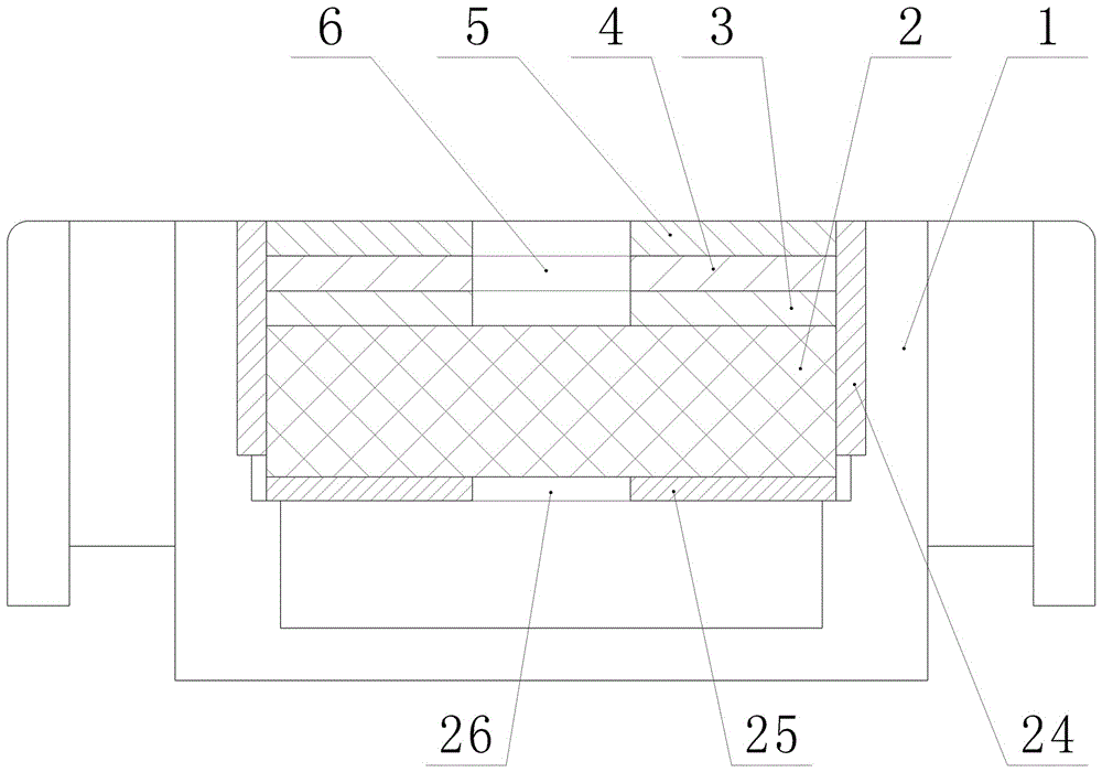
[0041] refer to figure 1 , an engine intake air magnetization energy saving and emission reduction device, comprising a magnetizer arranged in a housing 1, the magnetizer includes

[0042] the first permanent magnet 2;

[0043] The first magnetically conductive metal sheet 3, the second magnetically conductive metal sheet 4 and the nonmagnetically conductive material sheet 5, the first magnetically conductive metal sheet 3, the second magnetically conductive metal sheet 4 and the nonmagnetically conductive material sheet 5 are sequentially stacked , the middle part of the first magnetically conductive metal sheet 3, the second magnetically conductive metal sheet 4 and the non-magnetically conductive material sheet 5 is provided with a first cavity 6;

[0044] A shielding sleeve 24 and a shielding layer 25, the middle part of the shielding layer 25 is provided with a shielding layer through hole 26;

[0045] One end surface of the first magnetically conductive metal sheet 3 ...

Embodiment 2

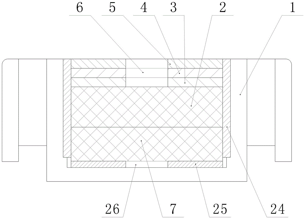
[0054] refer to Figure 5 , an engine intake air magnetization energy saving and emission reduction device, comprising a magnetizer arranged in a housing 1, the magnetizer includes

[0055] the first permanent magnet 2;

[0056]The first magnetically conductive metal sheet 3, the second magnetically conductive metal sheet 4 and the nonmagnetically conductive material sheet 5, the first magnetically conductive metal sheet 3, the second magnetically conductive metal sheet 4 and the nonmagnetically conductive material sheet 5 are sequentially stacked , the middle part of the first magnetically conductive metal sheet 3, the second magnetically conductive metal sheet 4 and the non-magnetically conductive material sheet 5 is provided with a first cavity 6;

[0057] A shielding sleeve 24 and a shielding layer 25, the middle part of the shielding layer 25 is provided with a shielding layer through hole 26;

[0058] One end surface of the first magnetically conductive metal sheet 3 i...


PUM


Abstract

The invention discloses an air magnetizing energy-saving emission-reducing device for engine inlet air. The air magnetizing energy-saving emission-reducing device comprises a magnetizer arranged in a housing, wherein the magnetizer comprises a first permanent magnet, a first magnetic conductive metal plate, a second magnetic conductive metal plate, a non-magnetic material plate, a shielding sleeve and a shielding layer; the first magnetic conductive metal plate, the second magnetic conductive metal plate and the non-magnetic material plate are sequentially in lap joint; a first cavity is formed in the middle parts of the first magnetic conductive metal plate, the second magnetic conductive metal plate and the non-magnetic material plate; a shielding layer through hole is formed in the middle of the shielding layer; one end surface of the first magnetic conductive metal plate is in lap joint with a first permanent magnet, and the other end surface of the first magnetic conductive metal plate is in lap joint with the shielding layer; and the first permanent magnet, the first magnetic conductive metal plate, the second magnetic conductive metal plate and the non-magnetic material plate are arranged in the shielding sleeve. According to the air magnetizing energy-saving emission-reducing device for the engine inlet air, after being magnetized, air molecules enter a combustion chamber, and the air molecules are quickly promoted to be tightly combined with fuel molecules, so that the fuel is sufficiently combusted to achieve better energy-saving emission-reducing effects.

Description

technical field [0001] The invention relates to engine accessories, in particular to an engine intake air magnetization energy saving and emission reduction device for magnetizing and supplementing the air entering the engine. Background technique [0002] In order to enhance the atomization effect of fuel oil, reduce exhaust CO and HC emissions, and save fuel consumption, the technology of magnetizing fuel oil through a magnetizer has been reported at home and abroad. However, since the fuel itself has no magnetic moment, the oil needs a relatively long saturation magnetization time under the action of a magnetic field, so the effect of the existing fuel magnetization device is not very ideal. [0003] In order to solve this problem, the patent "engine intake magnetization processing device" with publication number CN2594484Y discloses the structure as follows: the cover body is covered with the shell, and a cavity is formed inside, and there is a magnetized body in the cav...

Claims


Application Information

Patent Timeline
Patent Type & Authority Applications(China)
IPC IPC(8): F02M27/04
CPCF02M27/045Y02T10/12
Inventor 孟启平
Owner 刘华
Learn More