In-tunnel prefabricated cable tube and prefabricated water drainage pipe structure

A technology for cable pipes and drainage pipes, which is applied in the field of new cable passing through tunnels and drainage structures in tunnels. It can solve problems such as waste of investment, easy damage to the ditch body, and difficulty in setting up molds, so as to speed up the construction progress, reduce the tunnel section, Conducive to antifreeze effect

Inactive Publication Date: 2016-08-03
CHINA RAILWAY FIRST SURVEY & DESIGN INST GRP
View PDF5 Cites 2 Cited by
  • Summary
  • Abstract
  • Description
  • Claims
  • Application Information

AI Technical Summary

Problems solved by technology

The longitudinal section of the drainage ditch is generally rectangular. The drainage ditch and the cable channel are all made of concrete. The cover plate is a reinforced concrete prefabricated structure. The body is easily damaged, and seepage and water leakage often occur at the bottom of the ditch. The cover plate is prefabricated reinforced concrete, which is used in a large amount, and cannot be replaced flexibly when it is damaged and needs to be repaired. Due to the large overall size, the clear section of the tunnel is increased, resulting in waste of investment. And it cannot be exchanged flexibly when it is damaged and needs to be repaired

Method used


Image

  • In-tunnel prefabricated cable tube and prefabricated water drainage pipe structure

Examples


Embodiment Construction

[0019] The present invention will be described in detail below in conjunction with specific embodiments.

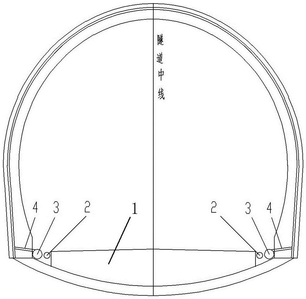
[0020] The present invention relates to a prefabricated cable tube and a prefabricated drainage tube structure in a tunnel. The prefabricated cable tube 2 and the prefabricated drainage tube 3 are laterally arranged side by side on the inner side of the tunnel lining arch foot and the outer side of the invert filling 1. A gap is provided between the lateral end of the invert filler 1 and the arch foot of the tunnel lining, and the prefabricated cable pipe 2 and the prefabricated drainage pipe 3 are located in the gap. The pipe diameter of the prefabricated drain pipe 3 is larger than the prefabricated cable pipe 2, and the prefabricated drain pipe 3 is located outside the prefabricated cable pipe 2. The diameter of the prefabricated drainage pipe 3 can be flexibly adjusted according to the water output, and the diameter of the prefabricated cable pipe 2 can be flexibly adjus...


PUM


Abstract

The invention relates to an in-tunnel prefabricated cable tube and a prefabricated water drainage pipe structure. In current tunnel engineering, the longitudinal cross-section of a water drainage ditch is commonly rectangular; a cable trough with a relatively small section area is formed in the outer side of the water drainage ditch; the water drainage ditch and the cable trough are made of concrete materials with relatively great dose, and cannot be flexibly changed when maintenance is needed once breakage happens. According to the invention, the prefabricated cable pipe and the prefabricated water drainage pipe are transversely arranged side by side at the inner side of a tunnel lining arch foot and the outer side of an inverted arch filling outer side; the outer side pipe wall of the prefabricated water drainage pipe is provided with a water drainage hole; a water guide tube is arranged in the tunnel surrounding rocks; the water guide tube is inserted into the water drainage hole; the diameter of the prefabricated water drainage pipe is greater than that of the prefabricated cable pipe; and the prefabricated water drainage pipe is positioned at the outer side of the prefabricated cable pipe. The conventional rectangular ditch cable trough is changed into a circular prefabricated pipe structure, and the manufacturing cost of the adopted fabricated pipe is obviously lower than the dose of concrete of the ditch cable trough, so that the cost is saved; and the prefabricated pipe is directly laid, so that the work of constructing ditch wall concrete, prefabricating a cover plate and the like is saved, and therefore, the construction is greatly convenient.

Description

Technical field [0001] The invention relates to a novel cable passing tunnel and a drainage structure system in the tunnel, in particular to a prefabricated cable pipe and a prefabricated drainage pipe structure in the tunnel. Background technique [0002] In the existing tunnel engineering, the tunnel drainage structure mainly adopts the method of setting a drainage ditch on both sides of the inner side of the tunnel lining. The surrounding rock water of the tunnel is introduced into the drainage ditch through the joint action of waterproof board, geotextile, and blind pipe, and discharged outside the tunnel. A cable trough is provided on the outside for laying cables through the tunnel. The longitudinal section of the drainage ditch is generally rectangular. The drainage ditch and the cable channel are made of concrete materials. The cover plate is a prefabricated reinforced concrete structure. The amount is large. It is difficult to erect the form during the construction. The ...

Claims


Application Information

Patent Timeline
Patent Type & Authority Applications(China)
IPC IPC(8): E21F16/02E21F17/06
CPCE21F16/02E21F17/06
Inventor 张剑
Owner CHINA RAILWAY FIRST SURVEY & DESIGN INST GRP
Why Eureka
Try Eureka