
Electric driving system

A technology of electric drive and drive seat, which is applied in the direction of electric power devices, motor vehicles, transmission devices, etc., can solve the problems of poor safety and stability, large drive volume, and inconvenient maintenance, and achieve convenient maintenance and repair, accurate reduction ratio, and simple structure Effect

Inactive Publication Date: 2016-08-03
ZHEJIANG EP EQUIP
View PDF5 Cites 0 Cited by
  • Summary
  • Abstract
  • Description
  • Claims
  • Application Information

AI Technical Summary

Problems solved by technology

[0003] The invention provides an electric drive system aiming at the defects of large drive volume, complex structure, inconvenient maintenance, poor safety and stability, etc. in the electric drive system using a two-stage gear reduction box in the prior art.

Method used


Image

  • Electric driving system
  • Electric driving system
  • Electric driving system

Examples


Embodiment 1

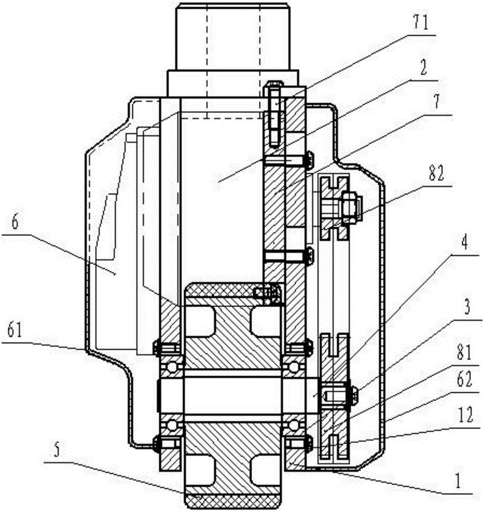
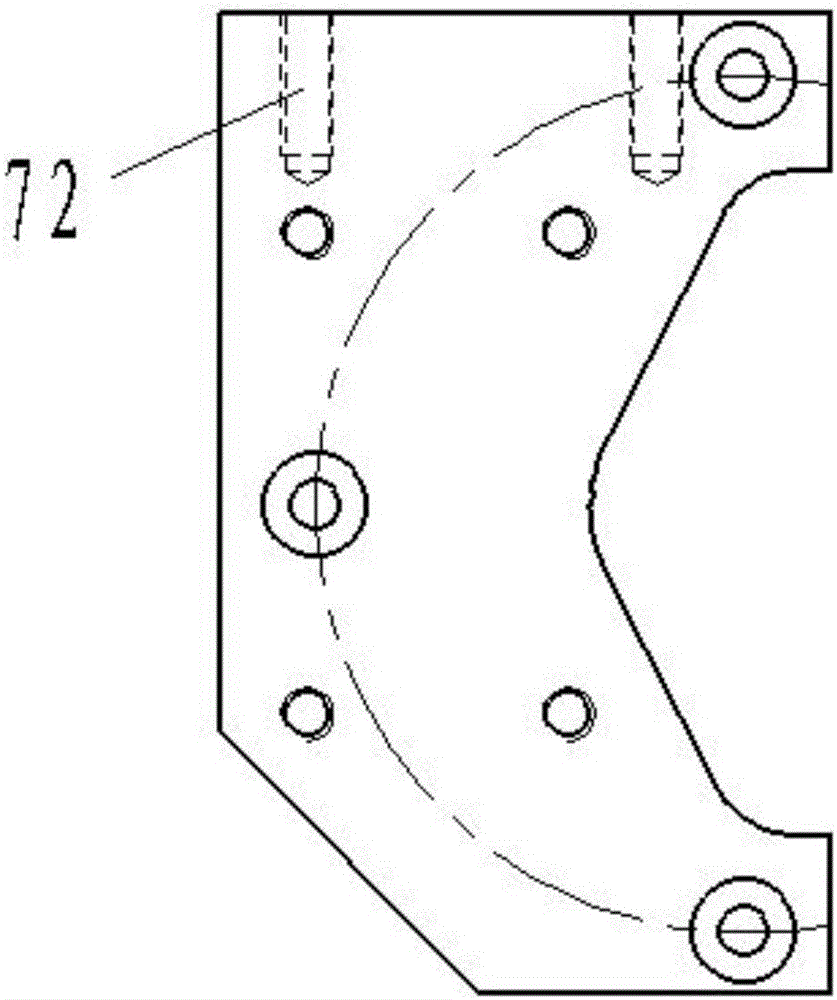
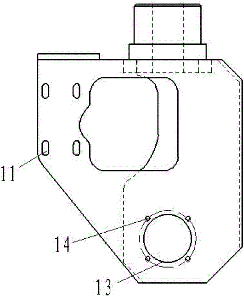
[0025] An electric drive system such as Figure 1-Figure 6 As shown, the drive base 1 is included, the drive base 1 is fixed with a motor mounting plate 7 by bolts, and the motor mounting plate 7 is provided with threaded mounting holes on the front, which can be installed on the drive base 1 by bolts; the motor mounting plate 7 is fixedly installed with Drive motor 2. The driving seat 1 is provided with a waist hole 11 for the bolt to move up and down, and the bolt passes through the waist hole 11 and is fixed in the threaded mounting hole to realize the fixing of the motor mounting plate 7. The waist hole 11 is arranged along the height direction, and the screw of the bolt The diameter of the cap part is greater than the width of the waist hole 11, and the height of the motor mounting plate 7 is changed by changing the position of the bolt in the waist hole 11. In this embodiment, the top of the motor mounting plate 7 is provided with a longitudinally arranged threaded moun...

Embodiment 2

[0031] The same as embodiment 1, the difference is that the drive shaft 4 in this embodiment is provided with a keyway, and the torque is transmitted between the middle part of the drive wheel and the drive shaft through a flat key, so that the drive wheel 5 rotates with the drive shaft 4, avoiding the drive shaft. The situation that the driving wheel cannot effectively and continuously output the driving force due to mutual rotation with the driving wheel.


PUM


Abstract

The invention relates to a driving system and discloses an electric driving system. The electric driving system comprises a driving seat (1), wherein a driving motor (2) is arranged on the driving seat (1); the driving seat (1) is also provided with a driving shaft (4) by virtue of a bearing (3); a driving wheel (5) is arranged on the driving shaft (4); the driving shaft (4) is a flat shaft; the middle part of the driving wheel (5) is provided with a flat opening (51) matched with the driving shaft (4); the driving shaft (4) rotates along with rotation of the driving wheel (5) by matching with the flat opening; the input end of the driving shaft (4) and an output shaft of the driving motor (2) are provided with chain wheels transmitted through mutual matching of chains. A low-speed motor with one-stage gear reduction function is matched with the chain wheels and the chains with two-stage reduction function, so that power output of the driving wheel (5) is realized; and with the mechanism, the driving system is simple in structure, small in output power loss, accurate in reduction rate and convenient to maintain and repair.

Description

technical field [0001] The invention relates to a driving system, in particular to an electric driving system used in handling equipment. Background technique [0002] At present, some logistics handling equipment is used in workshops or warehouses. With the improvement of technology, logistics handling equipment is gradually replaced by electric drive instead of human drive, which reduces the labor intensity of workers and greatly increases production efficiency. However, the general conventional electric drive system cannot be directly used to drive the tires due to the high speed of the drive motor and small output torque; in order to increase the torque of the drive system, a deceleration mechanism must be added in the drive box, usually using two-stage gear deceleration, As a result, the structure of the driving box is relatively complicated, the volume of the box is too large, and the phenomenon of driving oil leakage is prone to occur during the driving process, which...

Claims


Application Information

Patent Timeline
Patent Type & Authority Applications(China)
IPC IPC(8): B60K17/04B60K17/08
CPCB60K17/04B60K17/08B62B5/0043B62B3/0612B60K1/00F16H7/06F16H7/14
Inventor 许洪鹏金苗峰许林杰
Owner ZHEJIANG EP EQUIP
Learn More