Circular plastic impeller fixture

A technology of plastics and impellers, applied in the direction of clamps, manufacturing tools, etc., can solve problems such as product extrusion deformation, product processing quality problems, and affecting the company's product image, and achieve the effect of consistent working frequency and uniform circumferential force

Active Publication Date: 2016-08-03
NINGBO LANGDI IMPELLER MACHINERY
View PDF6 Cites 0 Cited by
  • Summary
  • Abstract
  • Description
  • Claims
  • Application Information

AI Technical Summary

Problems solved by technology

Especially in the processing field of air-conditioning accessories—impellers, the plastic impellers need to be clamped and positioned by fixtures during the processing; however, the fixtures equipped with the impellers are currently equipped with clamping parts in different directions to form a clamping station. These clamping parts in different directions are equipped with drive components, such as cylinders; therefore, the driving frequency of these clamping parts needs to be adjusted consistently, but even so, the frequency of multiple sets of drive pairs will be inconsistent after long-term use, and If the frequency of clamping parts is inconsistent in the clamping of plastic impellers, and the circumferential force of plastic impellers is uneven, it will cause inaccurate work positions, or product extrusion deformation, resulting in problems in product processing quality and affecting the company's product image

Method used


Image

  • Circular plastic impeller fixture
  • Circular plastic impeller fixture
  • Circular plastic impeller fixture

Examples


Embodiment 1

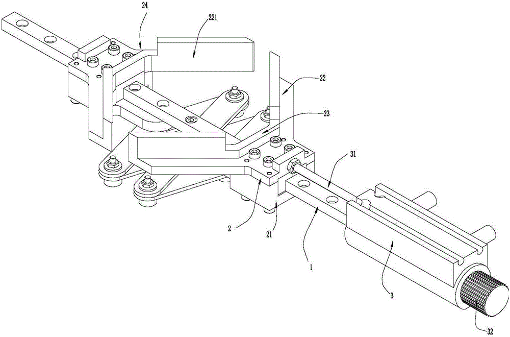
[0022] Such as Figure 1~Figure 3 The shown circular plastic impeller fixture includes a linear guide rail 1 and a clamping assembly slidably arranged on the linear guide rail 1 . The clamping assembly includes two sets of clamping parts 2 facing each other. The two sets of clamping parts 2 are linked together. There is one and only one set of clamping parts 2 connected to the output end of the driving part. The driving part drives the clamping part 2 Move along the track direction of the linear guide 1. Since the two sets of clamping components 2 are linked together, only one set of clamping components 2 needs to be driven by a driving component to realize the synchronous movement of the two sets of clamping components 2 . As shown in the figure, conventionally used driving components are cylinders 3, which are arranged at one end of the linear guide rail 1, and the output shaft 31 of the cylinder 3 is parallel to the linear guide rail 1 and connected to the clamping part 2....

Embodiment 2

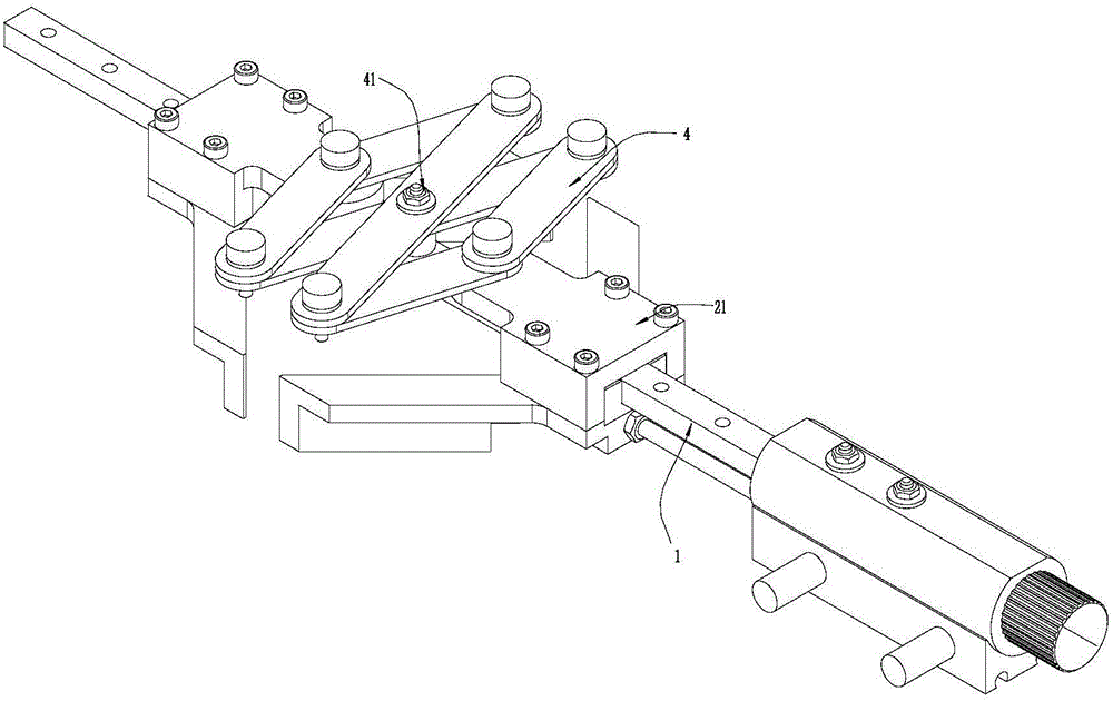
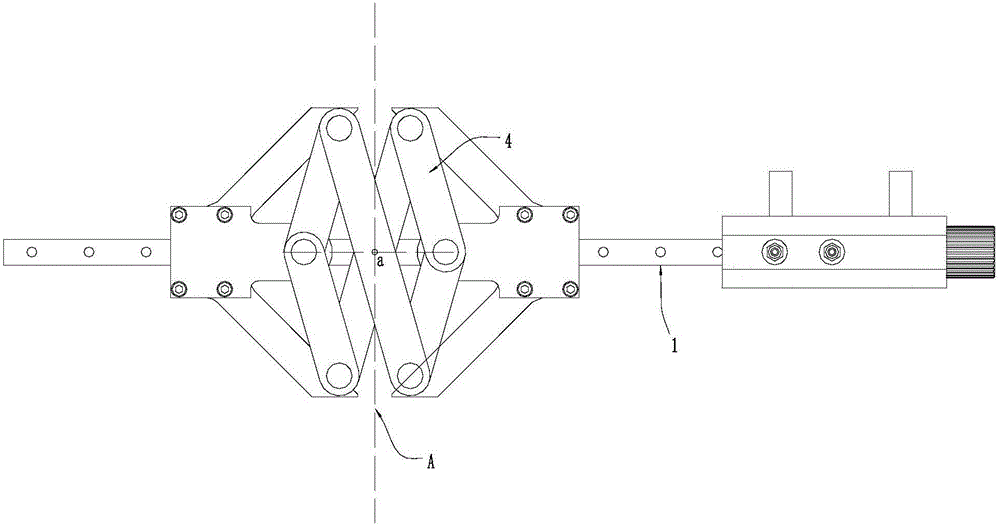
[0027] Such as Figure 4~Figure 6 Shown is the second embodiment of the circular plastic impeller clamp, which adopts the same inventive concept as the impeller clamp in Example 1, solves the same technical problem, and achieves the same invention purpose. The difference between this solution and Embodiment 1 is that in this solution, there are two linear guide rails 1, and the two linear guide rails 1 are arranged on the base plate 5 along the same axis, and a passage is opened on the base plate 5 between the two linear guide rails 1. Hole 51. The linkage assembly also adopts an X-shaped telescopic part 4, and the two ends of the X-shaped telescopic part 4 along the track direction of the linear guide rail 1 are respectively connected to two sets of clamping parts 2; There are two hinge points 41 on the top, and the two hinge points 41 are symmetrical to each other with the linkage pivot point a as the center. The two hinge points 41 are both slidably positioned on the base ...


PUM


Abstract

The invention relates to the field of mechanical fixtures, and discloses a circular plastic impeller fixture. The circular plastic impeller fixture comprises a linear guide rail, and a clamping module slidingly arranged on the linear guide rail; the clamping module includes two sets of opposite clamping parts; a clamping station is formed between the two sets of clamping parts; two clamping arms are arranged on the clamping parts; clamping end surfaces of the two clamping arms are perpendicular; two adjacent clamping end surfaces on the two sets of clamping parts are also perpendicular; the two sets of clamping parts are linked, and can make mirror image movement along a linkage axis surface; the linkage axis surface is a plane passing through a linkage axis point and being perpendicular to the direction of the linear guide rail; and the linkage axis point is a center point of the moving direction of the two sets of clamping parts. The impeller fixture clamps workpieces or products through two sets of clamping parts linked on the same linear rail; and the two sets of clamping parts are consistent in working frequency, so that the clamping station accuracy is guaranteed, and the product machining quality is guaranteed.

Description

technical field [0001] The invention relates to the field of mechanical clamps, in particular to a circular plastic impeller clamp. Background technique [0002] Fixtures are the general term for various clamping devices in the mechanical field. Fixtures are generally used in equipment to clamp workpieces to cooperate with equipment for workpiece processing. It can be said that fixtures are indispensable components in many mechanical processing equipment. In the field of processing plastic workpieces, plastic workpieces need to be processed after thermoplastic. At this time, the plastic workpieces are not completely cooled, and the plastic workpieces are easily deformed under pressure. In turn, the requirements for the clamping of plastic workpieces are relatively high. Especially in the processing field of air-conditioning accessories—impellers, the plastic impellers need to be clamped and positioned by fixtures during the processing; however, the fixtures equipped with the...

Claims


Application Information

Patent Timeline
Patent Type & Authority Applications(China)
IPC IPC(8): B25B5/06B25B5/16B25B5/02B25B5/14
CPCB25B5/02B25B5/061B25B5/14B25B5/163B25B5/166
Inventor 高文铭王银祥洪银川毛建东
Owner NINGBO LANGDI IMPELLER MACHINERY
Why Eureka
Try Eureka