
Real-time dynamic heart rate monitoring device and monitoring method

A technology of heart rate monitoring and real-time dynamics, applied in the electronic field, can solve the problems of high hardware cost, large resource overhead, and high computational complexity of algorithms

Active Publication Date: 2016-08-03
把脉(上海)信息科技有限公司
View PDF4 Cites 5 Cited by
  • Summary
  • Abstract
  • Description
  • Claims
  • Application Information

AI Technical Summary

Problems solved by technology

[0006] In view of the deficiencies in the prior art, the purpose of the present invention is to provide a real-time dynamic heart rate monitoring device and a monitoring method, aiming at solving the problem of high computational complexity of the algorithm, high hardware cost, and computational complexity of the dynamic heart rate monitoring device in the prior art when monitoring heart rate The disadvantage of high resource overhead in terms of storage and energy

Method used


Image

  • Real-time dynamic heart rate monitoring device and monitoring method
  • Real-time dynamic heart rate monitoring device and monitoring method

Examples


Embodiment Construction

[0048] In order to make the object, technical solution and effect of the present invention more clear and definite, the present invention will be further described in detail below. It should be understood that the specific embodiments described here are only used to explain the present invention, not to limit the present invention.

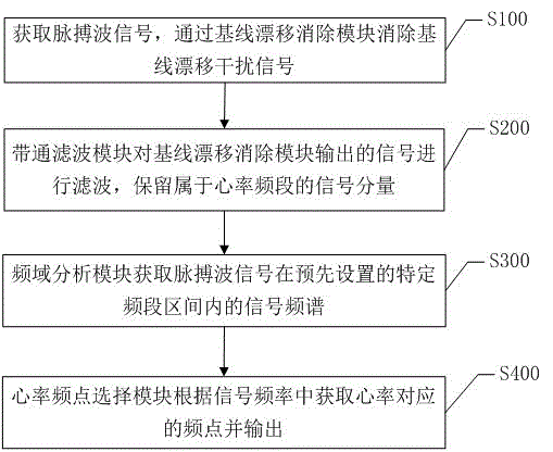
[0049] The present invention also provides a functional schematic diagram of a preferred embodiment of a real-time dynamic heart rate monitoring device, as figure 1 As shown, wherein, the device includes a baseline drift elimination module 100, a bandpass filter module 200, a frequency domain analysis module 300, and a heart rate frequency point selection module 400;

[0050]The baseline drift elimination module 100 is used to eliminate the interference signal that causes the baseline of the pulse wave signal to drift; the bandpass filter module 200 is used to obtain frequency signal components belonging to the heart rate frequency band while elim...


PUM


Abstract

The invention discloses a real-time dynamic heart rate monitoring device and monitoring method. The device comprises a baseline drift removal module, a band-pass filter module, a frequency domain analysis module and a heart rate frequency point selection module, wherein the baseline drift removal module is used for removing an interference signal of causing drift of the baseline of a pulse wave signal; the band-pass filter module is used for removing a noise signal out of a heart rate frequency band when obtaining a frequency signal component belonging to the heart rate frequency band; the frequency domain analysis module is used for obtaining a signal frequency spectrum of the pulse wave signal in a specific frequency band interval set in advance; the heart rate frequency point selection module is used for obtaining the frequency point corresponding to the heart rate and outputting the frequency point. The influences of human motion and muscle motion on heart rate analysis are eliminated; the hardware cost is reduced; the concerned frequency band interval can be flexibly selected; the frequency domain accuracy of the signal is improved only within the concerned frequency band; excessive computing and storage overheads are avoided.

Description

technical field [0001] The invention relates to the field of electronics, in particular to a real-time dynamic heart rate monitoring device and a monitoring method. Background technique [0002] With the application and development of mobile Internet technology in the medical and health field, a large number of different forms of smart watches, smart bracelets, and smart wristbands have appeared on the market, capable of measuring heart rate, blood pressure, blood oxygen concentration, respiratory rate, etc. Parameters of wearable mobile health products. Heart rate is defined as the number of heartbeats per minute of the human body, and is an important medical routine physiological parameter for evaluating the health status of a person. Heart rate monitoring is of great significance for disease risk early warning, disease diagnosis, and annual routine physical examination. In particular, sports such as fitness activities and outdoor running have extensive application requi...

Claims


Application Information

Patent Timeline
Patent Type & Authority Applications(China)
IPC IPC(8): A61B5/0245
CPCA61B5/0245A61B5/7203A61B5/7225A61B5/725
Inventor 许微伟邓瀚林
Owner 把脉(上海)信息科技有限公司
Learn More