Forming method of plastic material
A technology of plastic materials and forming molds, which is applied to household appliances, hollow objects, other household appliances, etc., can solve problems such as productivity decline and interruption of forming cycle, and achieve the effect of preventing the accumulation of oligomers and continuous forming operations.
- Summary
- Abstract
- Description
- Claims
- Application Information
AI Technical Summary
Problems solved by technology
Method used
Image

Examples
Embodiment 1
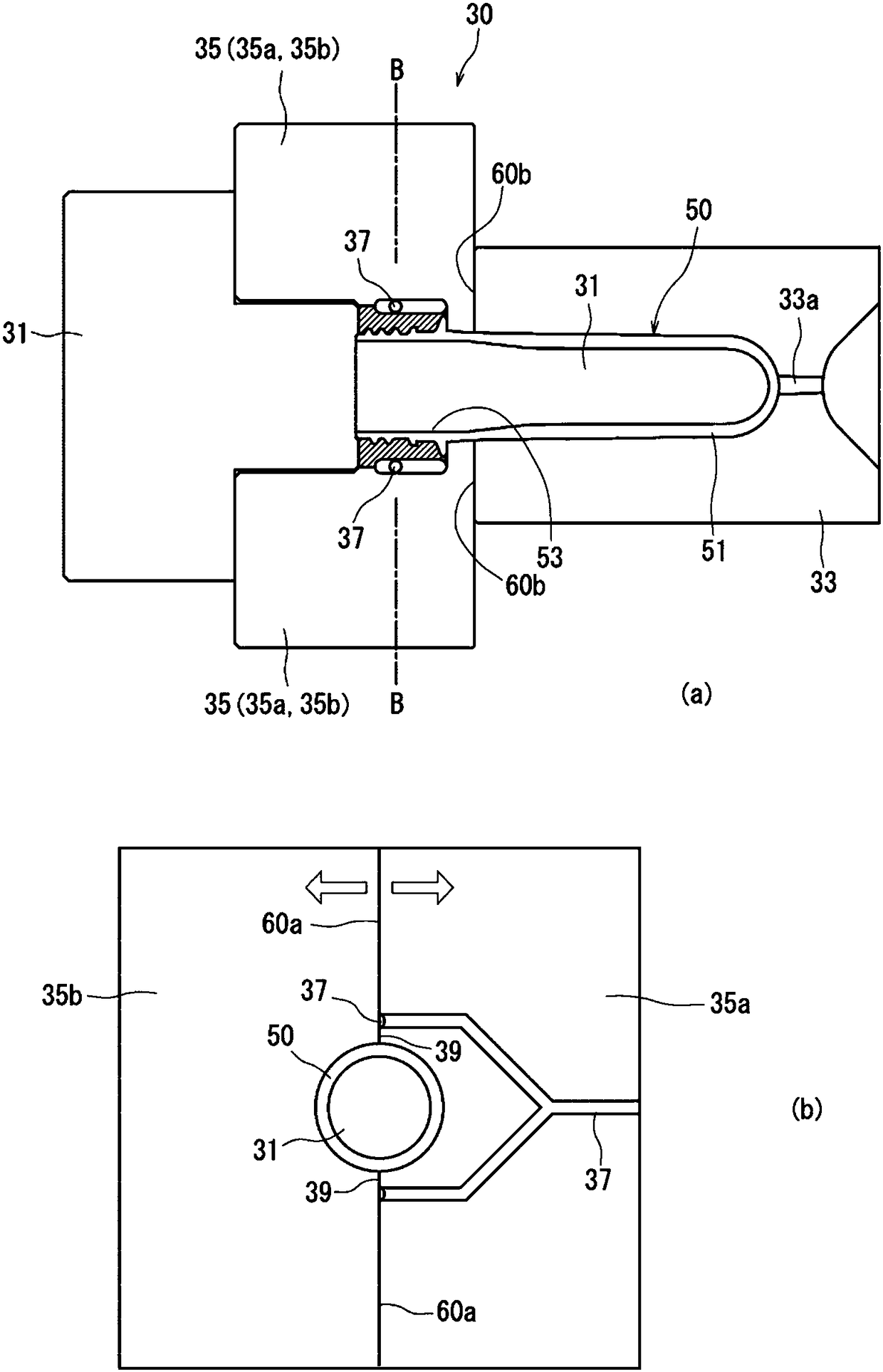
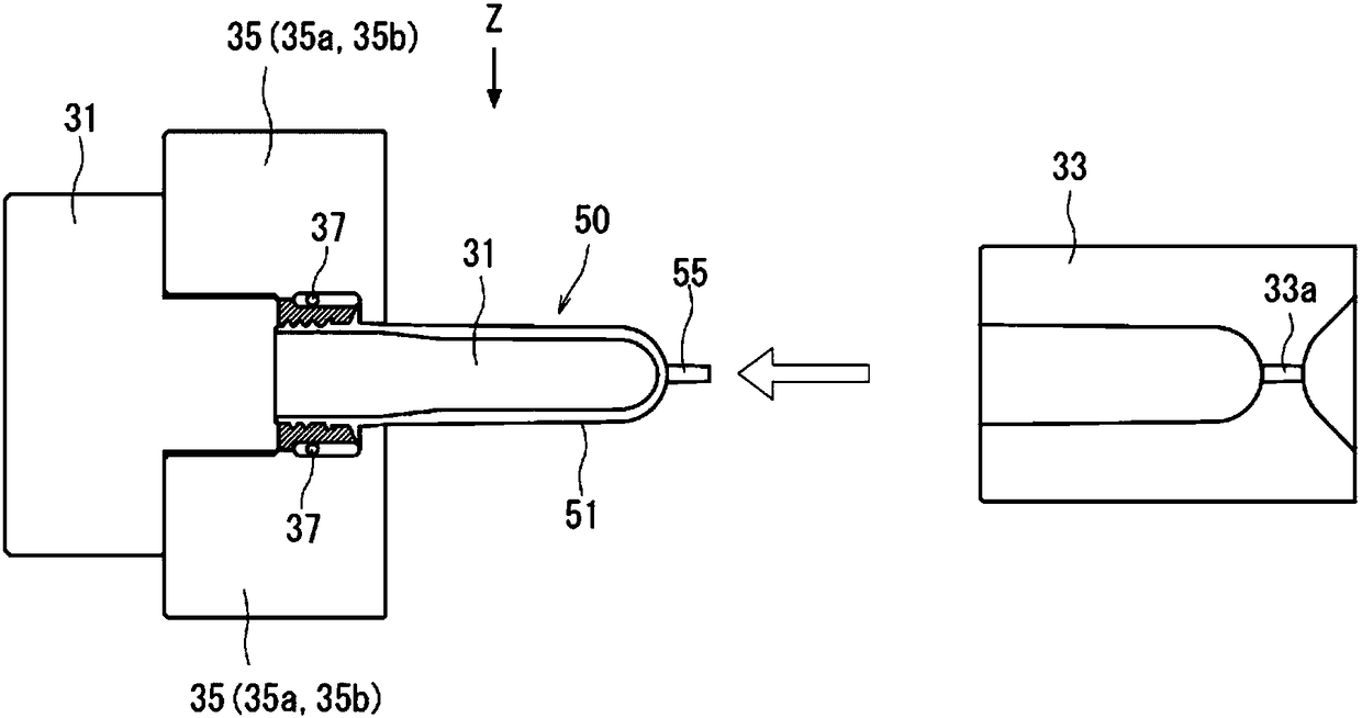
[0096] use has figure 2 The structure shown and the forming mold 30 maintained at 20°C. In the forming die 30, the parting dies 35a, 35b of the neck shell and the main body shell 31 are closed, and the exhaust hole 39 is formed by a discharge groove having a depth of about 20 μm and assuming that it is processed into a roughness of 0.70 μm. degree Ra of the bottom surface. The above molten PET for container molding is injected and filled into the cavity of the molding die 30, and sufficiently cooled in the cavity. Thereafter, the core 31 is slid relative to the main body shell 33, and the mold is opened (see image 3 ). Next, split the split molds 35a and 35b of the neck shell and open the split molds 35a and 35b to take out the preform 50 for a test tube shaped container (refer to Figure 4 ).
[0097] Then, before entering the next injection step, the parting molds 35a and 35b of the neck shell are Figure 5 Closed as shown (vent 39 has been formed at this stage). Th...
Embodiment 2
[0101] After the parting molds 35a and 35b of the neck shell are closed, the core 31 and the main body shell 33 such as Figure 5 In the unclosed state as shown, the air of 5 MPa is introduced into the discharge groove (the mold corresponding to the exhaust hole 39) through the gas flow path 37 near the split surface (the mating surface of the parting molds 35a and 35b of the neck shell). surface) for 1.5 seconds while allowing air to leak to the outside of the mold. After that, the core 31 and the main body case 33 are closed, and the next injection step is performed.
[0102] After repeating the above-mentioned steps 1000 times as in Example 1, it was checked visually whether oligomers adhered to the discharge grooves of the parting dies 35a and 35b of the neck casing. Little to no accumulation of oligomers.
Embodiment 3
[0104] After the parting molds 35a and 35b of the neck shell are closed, the core 31 is inserted, and after having Image 6 With the cavity corresponding to the neck 53 of the preform 50 formed as shown, air of 5 MPa was introduced through the gas flow path 37 for 1.5 seconds, and the air was leaked to the outside of the mold. Thereafter, the main body case 33 is closed and the next injection step is performed.
[0105] After repeating the above steps 1,000 times in the same manner as in Example 1, the molding machine was stopped, and it was observed with eyes to confirm whether the oligomer was attached to the vent hole 39 (the discharge grooves of the parting molds 35a and 35b of the neck shell and the cores). 31 on the surface opposite to the discharge groove). Little to no accumulation of oligomers.
PUM
| Property | Measurement | Unit |
|---|---|---|
| surface roughness | aaaaa | aaaaa |
Abstract
Description
Claims
Application Information
 - R&D
- Intellectual Property
- Life Sciences
- Materials
- Tech Scout
- Unparalleled Data Quality
- Higher Quality Content
- 60% Fewer Hallucinations
Browse by: Latest US Patents, China's latest patents, Technical Efficacy Thesaurus, Application Domain, Technology Topic, Popular Technical Reports.
© 2025 PatSnap. All rights reserved.Legal|Privacy policy|Modern Slavery Act Transparency Statement|Sitemap|About US| Contact US: help@patsnap.com