Closed electrical rotating machine
A rotary motor, sealed technology, applied in the direction of electrical components, electromechanical devices, electric components, etc., can solve problems such as copper loss, and achieve the effect of ensuring heat dissipation
- Summary
- Abstract
- Description
- Claims
- Application Information
AI Technical Summary
Method used
Image
Examples
Embodiment approach 1
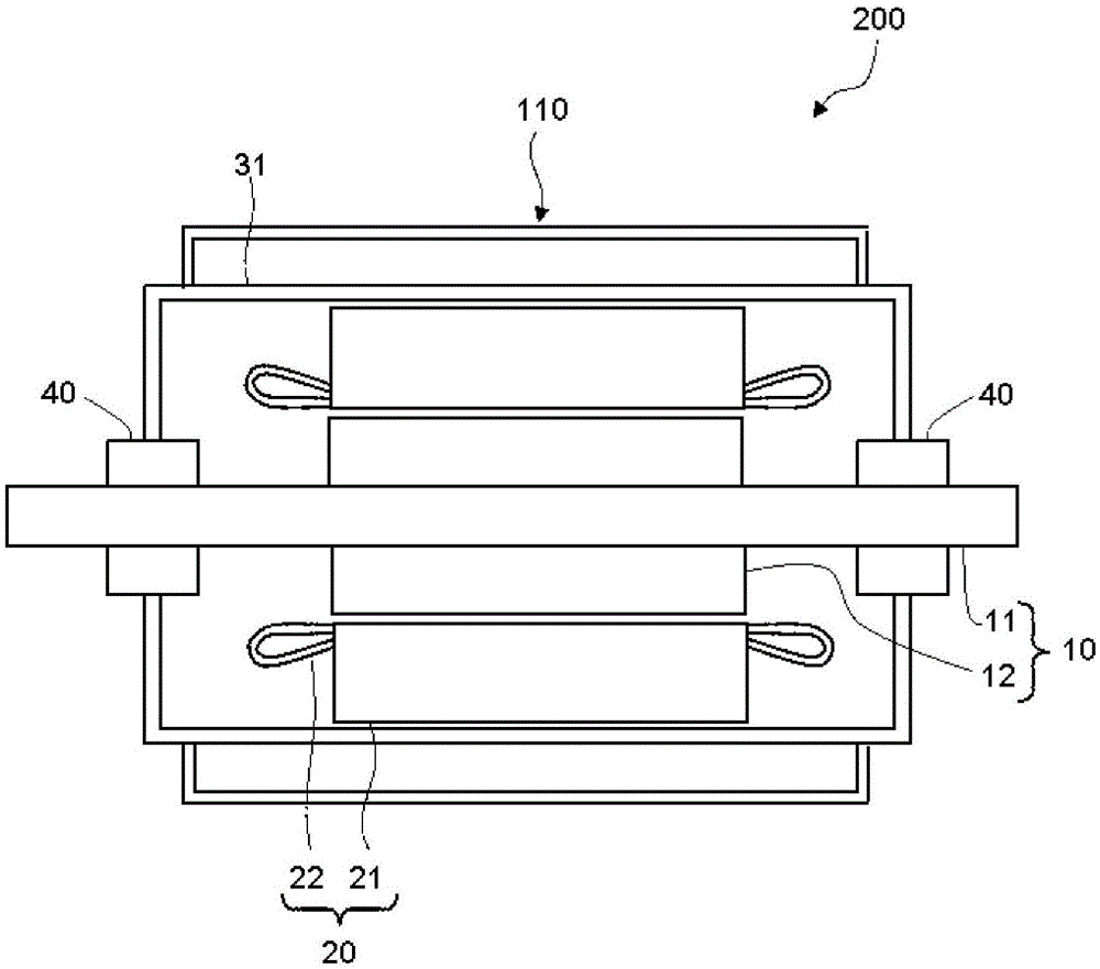
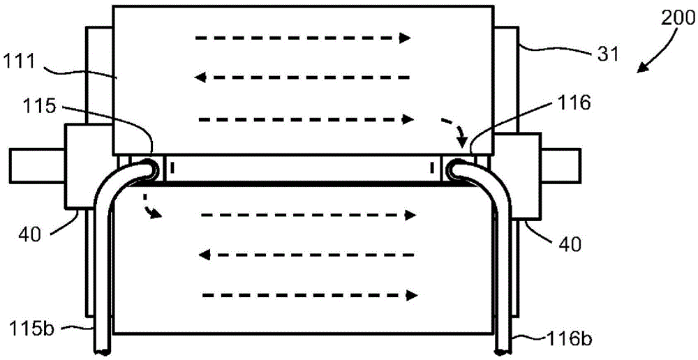
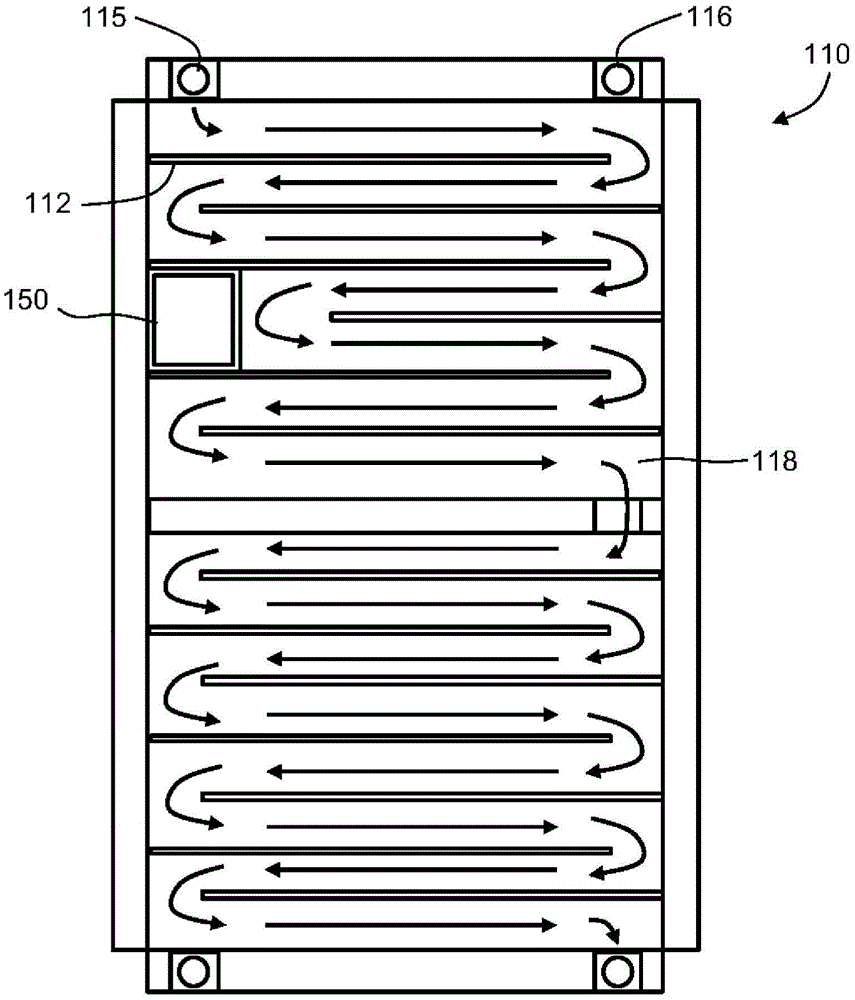
[0027] figure 1 It is a front sectional view showing the structure of the sealed rotating electrical machine according to Embodiment 1. The sealed rotating electric machine 200 has a rotor 10 , a stator 20 , a frame 31 , bearings 40 , and an external cooling structure 110 .
[0028] The rotor 10 has a rotating shaft 11 rotatably supported at both ends, and a cylindrical rotor core 12 fixed to the radially outer side of the rotating shaft 11 . The stator 20 has a cylindrical stator core 21 and a stator coil 22. The stator core 21 is statically fixed on the radially outer side of the rotor core 12 and is opposite to the rotor core 12. The stator coil 22 is laid in a slot not shown in the figure. The slots are formed in the vicinity of the inner surface of the stator core 21 , are arranged parallel to each other at intervals in the circumferential direction, and extend in the axial direction.
[0029] The frame 31 has a cylindrical shape and extends in the axial direction, acco...
Embodiment approach 2
[0044] This embodiment is a modification of the first embodiment. In the second embodiment, the partition member forming the coolant flow path inside the closed space 118 is different from the first embodiment. Figure 4 is a side view of the sealed rotating electrical machine according to Embodiment 2, but as Figure 4As shown, the appearance of the second embodiment is the same as that of the first embodiment.
[0045] Figure 5 It is a circumferential development view of the external cooling structure of the sealed rotating electrical machine of Embodiment 2. The structure of the flow path of the external cooling structure 120 is the same as that of Embodiment 1, and the flow direction is formed in an axial direction and alternately reversed. A plurality of first short partitions 122 and a plurality of second short partitions 123 are included as partition members. That is, a plurality of first short partitions 122 and a plurality of second short partitions 123 are arran...
Embodiment approach 3
[0051] This embodiment is a modification of the first embodiment. Figure 6 It is a side view of the sealed rotating electric machine according to Embodiment 3. In Embodiment 3, the cooler cover plate 131 is provided on the entire periphery except for the injection portion 115 and the discharge portion 116 .
[0052] Figure 7 It is a circumferential development view of the external cooling structure of the sealed rotating electrical machine of Embodiment 3. In this embodiment, a spiral partition plate 133 is provided as a partition member of the external cooling structure 130 . The spiral partition plate 133 is perpendicular to the axial direction and inclined along the circumferential direction, that is, installed in a spiral shape. In this embodiment, the flow path of the cooling medium is a flow path in only one direction. That is, the cooling medium flowing into the sealed space 118 from the injection part 115 advances in the circumferential direction in the sealed sp...
PUM
 Abstract
Description
Claims
Application Information
 - R&D Engineer
- R&D Manager
- IP Professional
- Industry Leading Data Capabilities
- Powerful AI technology
- Patent DNA Extraction
Browse by: Latest US Patents, China's latest patents, Technical Efficacy Thesaurus, Application Domain, Technology Topic, Popular Technical Reports.
© 2024 PatSnap. All rights reserved.Legal|Privacy policy|Modern Slavery Act Transparency Statement|Sitemap|About US| Contact US: help@patsnap.com


