Energy-saving control system for building

A control system and building energy-saving technology, applied in general control systems, control/regulation systems, program control, etc., can solve the problems of unreasonable distribution of heat, inability to adjust, energy waste, etc., to improve energy utilization and stable operation. , to avoid the effect of wasting energy

Inactive Publication Date: 2016-07-27
SHISHI GUOGAO ELECTRONICS TECH
View PDF9 Cites 0 Cited by
  • Summary
  • Abstract
  • Description
  • Claims
  • Application Information

AI Technical Summary

Problems solved by technology

[0002] Existing buildings with central heating in winter usually use a unified heating pipeline, regardless of whether there are people living in the room, they will be heated. When the house is idle, the energy waste is very large. At the same time, different heating subsystems cannot Adjustment, the heat can not be distributed reasonably, resulting in waste of resources

Method used


Image

  • Energy-saving control system for building

Examples


Embodiment 1

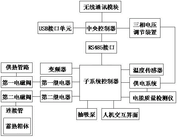
[0024] Such as figure 1 As shown, a building energy-saving control system includes a central controller and several control cabinets connected to the central controller, the control cabinets are used to control the opening and closing of the building heating pipeline, and the The control cabinets are respectively equipped with power supply systems, and subsystem controllers are respectively arranged in the control cabinets. The subsystem controllers are connected to the central controller through lines, and the power supply systems are respectively set There is a power quality detector, and the central controller is respectively connected to the power quality detector through lines, and a three-phase voltage regulator is arranged on the central controller, and the three-phase voltage regulator is respectively It is connected with the power supply system, a frequency converter is respectively arranged in the control cabinet, and the frequency converter is connected with the sub...

Embodiment 2

[0027] In this embodiment, on the basis of Embodiment 1, in order to improve the heat dissipation efficiency during heating, in this embodiment, preferably, a connecting pipe is arranged outside the building heating pipeline, and on the connecting pipe A second solenoid valve is provided, and a second relay for driving the second solenoid valve to open and close is provided on the subsystem controller. By increasing the connecting pipes, the heat transfer area between the high-temperature hot water and the outside is increased, and the heating efficiency can be improved conveniently.

[0028] In order to store the heat in the heat supply pipeline conveniently when it is not needed, in this embodiment, preferably, a heat storage box is provided on the connecting pipe, and a heat storage box is provided in the heat storage box. Heat storage material.

[0029] In order to improve the heat storage effect, in this embodiment, preferably, the adsorption heat storage material is pro...


PUM


Abstract

The invention discloses an energy-saving control system for a building. The system comprises a central controller and multiple control cabinets which are connected with the central controller, the control cabinets are used for controlling a heat supply pipeline of the building to be switched on and off, each control cabinet is provided with a power supply system and internally provided with a sub-system controller, each sub-system controller is connected with the central controller through a line, each power supply system is provided with a power quality detector, the central controller is connected with the power quality detectors through lines respectively, a three-phase voltage adjusting device is arranged on the central controller and connected with the power supply systems, and each control cabinet is internally provided with a frequency converter. According to the energy-saving control system, the heat supply pipeline is controlled to be switched on and off through solenoid valves, heat supply for sub-systems where the different control cabinets are located can be adjusted, heat is distributed reasonably, and energy waste is avoided.

Description

technical field [0001] The invention relates to a building energy saving control system. Background technique [0002] Existing buildings with central heating in winter usually use a unified heating pipeline, regardless of whether there are people living in the room, they will be heated. When the house is idle, the energy waste is very large. At the same time, different heating subsystems cannot If it is adjusted, the heat cannot be distributed reasonably, resulting in a waste of resources. Contents of the invention [0003] The purpose of the present invention is to provide a building energy-saving control system, which can improve the problems existing in the prior art. By using the solenoid valve to control the opening and closing of the heating pipeline, the heating adjustment of the subsystems where different control cabinets are located is realized. Realize the reasonable distribution of heat and avoid energy waste. [0004] The present invention is realized throug...

Claims


Application Information

Patent Timeline
Patent Type & Authority Applications(China)
IPC IPC(8): G05B19/042
CPCG05B19/042G05B2219/25314
Inventor 涂意
Owner SHISHI GUOGAO ELECTRONICS TECH
Why Eureka
Try Eureka