
Indoor 3D positioning system and method based on inertial sensor

An inertial sensor and positioning system technology, applied in the field of indoor 3D positioning systems based on inertial sensors, can solve the problems of complex floor structure, lack of height information, and reduced positioning accuracy.

Inactive Publication Date: 2018-05-22
WUHAN UNIV OF TECH
View PDF6 Cites 0 Cited by
  • Summary
  • Abstract
  • Description
  • Claims
  • Application Information

AI Technical Summary

Problems solved by technology

[0002] In modern society, with the continuous development of science and technology, more and more location-based positioning services are used in daily life, such as Gaode map and Google map, etc., which are commonly used in daily life. The development of such services is Based on the Global Positioning System (GPS), GPS positioning services are now very mature and can achieve high positioning accuracy. However, the main application scenarios for GPS positioning services are outdoors without shelter. There will be a canyon effect indoors, and it cannot work normally, which is reflected in the instability of the signal and the obvious decline in positioning accuracy. Therefore, GPS has a positioning bottleneck and is not suitable for indoor positioning.
[0003] The issue of indoor positioning has received more and more attention, and people's demand for indoor positioning is increasing day by day. Now there are a large number of indoor positioning technologies, such as infrared-based indoor positioning technology, ultra-wideband-based positioning technology, based on RFID indoor positioning technology and WiFi-based indoor positioning technology have their own advantages and disadvantages. Generally speaking, this type of positioning technology focuses on indoor 2D positioning services, but the current floor structure is complex and 2D indoors lacking height information. Positioning, often cannot meet the current indoor positioning needs

Method used


Image

  • Indoor 3D positioning system and method based on inertial sensor
  • Indoor 3D positioning system and method based on inertial sensor
  • Indoor 3D positioning system and method based on inertial sensor

Examples


Embodiment Construction

[0073] Below in conjunction with accompanying drawing and specific embodiment the present invention is described in further detail:

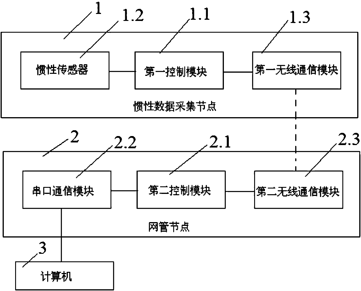
[0074] Such as figure 1 The indoor 3D positioning system based on inertial sensors includes an inertial data acquisition node 1, a network management node 2 and a computer 3, wherein the inertial data acquisition node 1 includes a first control module 1.1, an inertial sensor 1.2 and a first wireless Communication module 1.3, the network management node 2 includes a second control module 2.1, a serial port communication module 2.2 and a second wireless communication module 2.3, wherein the signal output end of the inertial sensor 1.2 is connected to the signal input end of the first control module 1.1, the first The signal output end of the control module 1.1 is connected to the signal input end of the first wireless communication module 1.3, the signal output end of the second wireless communication module 2.3 is connected to the signal input en...


PUM


Abstract

The invention discloses an indoor 3D positioning system based on an inertial sensor. The signal output end of the inertial sensor of the indoor 3D positioning system is connected with the signal input end of a first control module, the signal output end of the first control module is connected with the signal input end of a first wireless communication module, the signal output end of a second wireless communication module is connected with the signal input end of a second control module, the signal output end of the second control module is connected with the data communication end of a computer through a serial port communication module, and the first wireless communication module is in wireless communication with the second wireless communication module. By means of the indoor 3D positioning system, accurate indoor 3D positioning can be achieved.

Description

technical field [0001] The present invention relates to the technical field of indoor positioning, in particular to an indoor 3D positioning system and method based on inertial sensors. Background technique [0002] In modern society, with the continuous development of science and technology, more and more location-based positioning services are used in daily life, such as Gaode map and Google map, etc., which are commonly used in daily life. The development of such services is Based on the Global Positioning System (GPS), GPS positioning services are now very mature and can achieve high positioning accuracy. However, the main application scenarios for GPS positioning services are outdoors without shelter. There will be a canyon effect indoors, and it cannot work normally, which is reflected in the instability of the signal and the obvious decline in positioning accuracy. Therefore, GPS has a positioning bottleneck and is not suitable for indoor positioning. [0003] The is...

Claims


Application Information

Patent Timeline
Patent Type & Authority Patents(China)
IPC IPC(8): G01C21/20G01C21/16
CPCG01C21/16G01C21/206
Inventor 李方敏谢鹏李扬帆陈晓闯刘果刘新华
Owner WUHAN UNIV OF TECH
Learn More