
Automatic compensation type vacuum tube connecting device and dredging machinery with connecting device

A technology of automatic compensation and connection device, which is applied to expansion compensation device, adjustable connection, mechanical equipment and other directions for pipelines, can solve problems such as affecting the safety of driving operations, reducing the carrying capacity of vehicles, increasing the quality of the whole vehicle, etc. The effect of convenient installation and maintenance, reducing the weight of the whole vehicle and increasing the carrying capacity

Active Publication Date: 2016-07-27
厦门威迪思汽车设计服务有限公司
View PDF5 Cites 0 Cited by
  • Summary
  • Abstract
  • Description
  • Claims
  • Application Information

AI Technical Summary

Problems solved by technology

These special vehicles for sanitation use vacuum pumps to connect with the sewage tanks through vacuum tubes. When the pollutants in the sewage tanks need to be cleaned up after the sewage suction operation is completed, the tanks need to rotate around the rotation axis of the sub-frame. In order to ensure the sealing of the connection between the vacuum pump and the tanks The connection pipe between them is generally made as a whole around the outside of the sewage tank and a large part protrudes. This design affects the appearance of the vehicle and the protruding part is easy to scratch with external disturbances, which affects the safety of driving operations. The length of the wound vacuum tube is large, which increases the mass of the vehicle, reduces the carrying capacity of the vehicle, and increases energy consumption

Method used


Image

  • Automatic compensation type vacuum tube connecting device and dredging machinery with connecting device
  • Automatic compensation type vacuum tube connecting device and dredging machinery with connecting device
  • Automatic compensation type vacuum tube connecting device and dredging machinery with connecting device

Examples


Embodiment Construction

[0023] In order to further explain the technical solutions of the present invention, specific examples are given below to illustrate in detail.

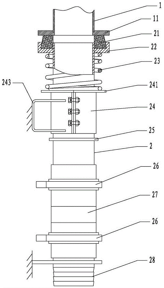
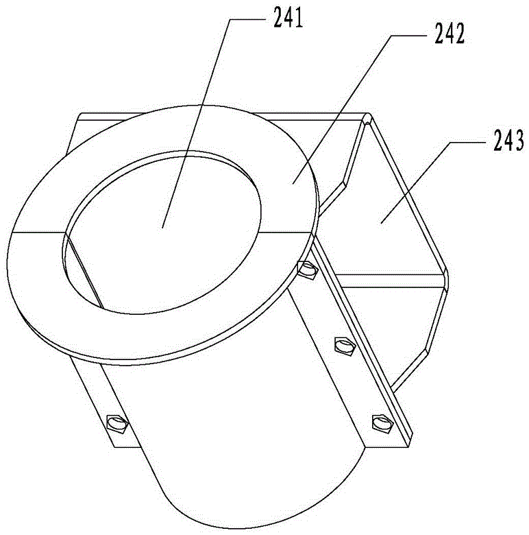
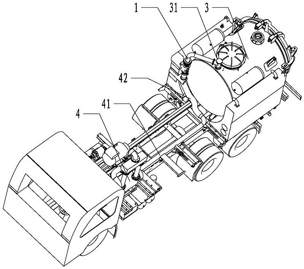
[0024] Such as Figure 1 to Figure 5 As shown, an automatic compensation type vacuum pipe connection device and dredging machine with the connection device include a dynamic connection pipe 1 and a static connection pipe 2 that acts as a connection guide. Among them, the dynamic connecting pipe 1 is a 90-degree bent pipe, and the upper horizontal end is provided with a flange connected to the side flange of the automatic shut-off valve 31 on the sewage tank 3, and the vertical lower end of the dynamic connecting pipe 1 is provided with a static connecting pipe 2 The ring flange 11 of the connecting end port sealing connection. On the static connecting pipe 2, the connecting end of the moving connecting pipe 1 is set with a sealing rubber 21, a concave ring 22, a spring 23 and a circular pipe guide seat 24 sequentially from top to bo...


PUM


Abstract

The invention relates to an automatic compensation type vacuum tube connecting device and a dredging machinery with the connecting device. The connecting device is characterized by comprising a dynamic connecting pipe and a static connecting pipe; an annular flange is arranged in a port of a connecting end of the dynamic connecting pipe with the static connecting pipe; a sealing rubber, a concave ring, a spring and a circular pipe guide base coat a connecting end of the static connecting pipe with the dynamic connecting pipe from top to bottom in sequence; the top of the sealing rubber is butted against the annular flange, and the bottom is arranged in the concave ring; and the spring is butted against between the bottom of the concave ring and the top of the circular pipe guide base. The vacuum pipe connecting device consisting of the dynamic connecting pipe and the static connecting pipe can be connected and preferably sealed in the dirt sucking operation, can be released when unloading a sewage tank, and can eliminate errors generated in the manufacturing process and higher pressure stress generated in the joint process of the dynamic connecting pipe and the static connecting pipe.

Description

technical field [0001] The invention relates to the field of sludge and sewage purification treatment, and relates to a special municipal sanitation machine for dredging, cleaning and absorbing sewers and septic tanks, in particular to a pipe joint used to connect the sewage tank of a dredging vehicle and the hose of a vacuum pump device. Background technique [0002] In the past 20 years, with the rapid development of urban construction in my country, the coverage of urban sewers has also increased rapidly. However, municipal management still focuses on construction and neglects maintenance, especially in pipeline maintenance and maintenance technology. In the past 10 years, sewage suction and dredging machinery for urban sewers and septic tanks in my country have developed rapidly. [0003] At present, there are three types of special municipal sanitation vehicles used for dredging, cleaning and suctioning sewers and septic tanks in the market in my country: sewage suctio...

Claims


Application Information

Patent Timeline
Patent Type & Authority Applications(China)
IPC IPC(8): F16L51/00F16L27/12
CPCF16L27/12F16L51/00
Inventor 谭璀璨欧阳联格尹鹏
Owner 厦门威迪思汽车设计服务有限公司
Learn More