Wall for hot gas channel in gas turbine

A gas turbine, hot gas technology, applied in the cooling, combustion chamber, combustion method of turbine/propulsion device, etc., can solve problems such as limited life, and achieve the effect of increasing tolerance and increasing quantity

Inactive Publication Date: 2016-07-27
ANSALDO ENERGIA SWITZERLAND AG
View PDF6 Cites 1 Cited by
  • Summary
  • Abstract
  • Description
  • Claims
  • Application Information

AI Technical Summary

Problems solved by technology

However, life is still limited, and once a defect (such as a crack) begins to appear, the part must be replaced immediately because the damage tends to spread rapidly

Method used


Image

  • Wall for hot gas channel in gas turbine
  • Wall for hot gas channel in gas turbine
  • Wall for hot gas channel in gas turbine

Examples


Embodiment Construction

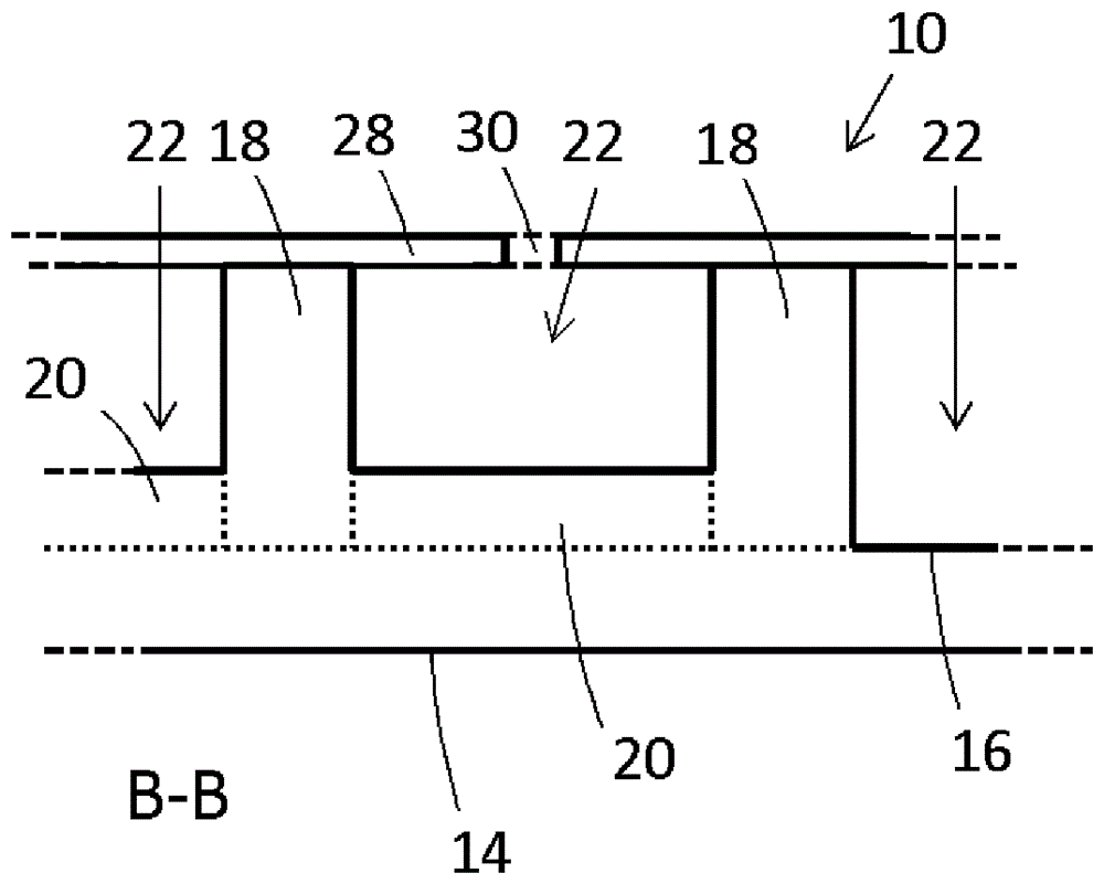
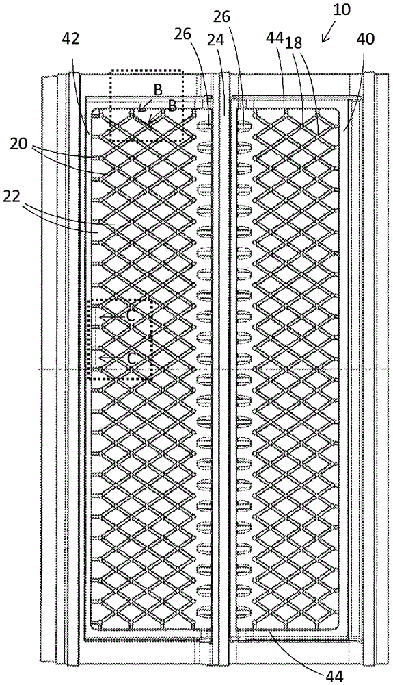
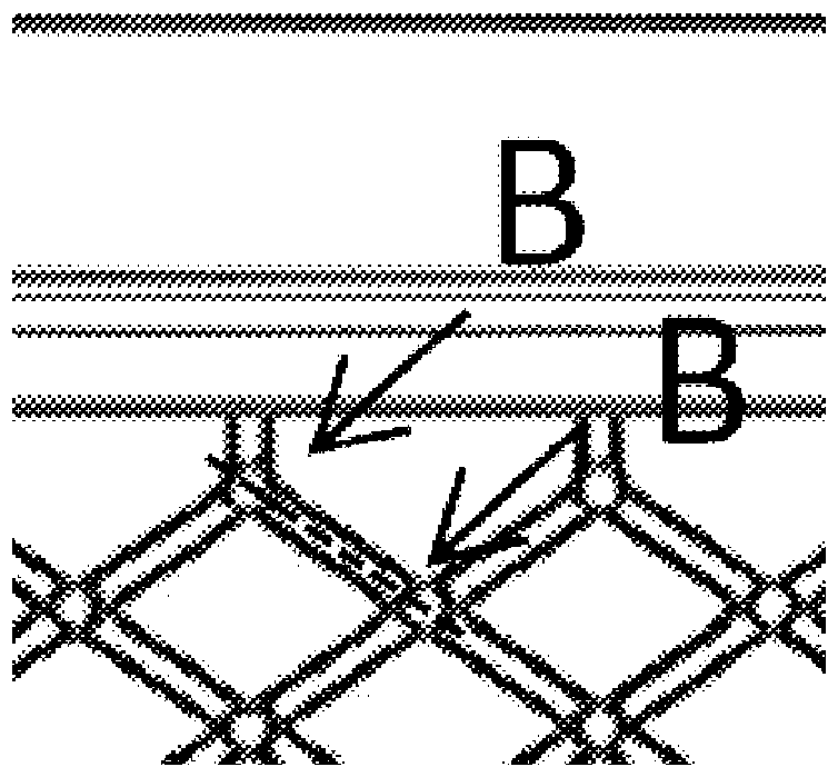
[0043] figure 1 and figure 2 (along figure 1 The cross-section of B-B in ) shows a wall 10 for a gas turbine exposed to a hot fluid, such as hot exhaust gas on the positive side 14 . On the back side 16 of the wall are attached an array of pins 18 . Ribs 20 extend between the pins and are attached to both the pins and the rear wall. The ribs define the cell 22 on the back side of the wall.

[0044] Optionally, a second wall 24 may be provided which is attached to the back side 16 of the wall and is substantially or completely perpendicular to the back side 16 . Stiffening ribs 26 may be attached to the wall and the second wall for structural support.

[0045] figure 2 Also shown is a strike plate 28 which is added near the pin. Impingement cooling holes 30 may be provided in the impingement plate 28 . The impingement cooling holes are typically located on the center of the element 22 such that figure 2 The impingement cooling holes shown in are actually set back be...


PUM


Abstract

A wall (10) for a hot gas channel in a gas turbine is described, the wall (10) having a back side (16) and a front side (14) and an impingement sheet comprising impingement cooling holes (30), the wall (10) being for exposure to a hot fluid at the front side (14), and the wall comprising an array of pins (18) attached to the back side (16) and extending between the back side (16) and the impingement sheet (28), the wall (10) additionally comprising a plurality of ribs (20) attached to the back side (16), each rib extending between two pins (18) to delineate an array of cells (22) on the back side (16), and / or at least one compartment wall (32) attached to the back side (16) to delineate compartments on the back side (16). Embodiments include an impingement sheet (28) with impingement cooling holes (30) and cooling exit holes (50). A gas turbine comprising the wall (10) described above and a method for use of the wall (10) are also described.

Description

technical field [0001] The present invention relates to gas turbines and, more particularly, to walls of hot gas paths for use in gas turbines. Background technique [0002] Various components in a gas turbine are subject to high temperatures and are therefore prone to degradation or breakdown. One such group of components is the internal hot gas surfaces or walls. These surfaces can be cooled from the backside (cold side) to improve their lifetime. However, the lifetime is still limited, and once a defect (such as a crack) starts to appear, the part must be replaced immediately because the damage tends to spread rapidly. This is especially true once any cracks become large enough to lose a significant amount of cooling air through the holes, reducing cooling effectiveness. As an example, an impingement cooled backside allows cracks or openings in the largest area of ​​the sum of all impingement holes feeding that area in order to keep working. [0003] It has thus been ...

Claims


Application Information

Patent Timeline
Patent Type & Authority Applications(China)
IPC IPC(8): F02C7/12
CPCF02C7/12F01D11/08F01D25/12F01D25/14F02K1/822F05D2240/11F05D2240/15F05D2240/81F05D2260/201F23R3/002F23R2900/03044F23R2900/03045F28F19/002Y02T50/60F05D2260/212F05D2260/22141
Inventor C.迪迪安H.布兰德M.科彻特R.科伊恩科
Owner ANSALDO ENERGIA SWITZERLAND AG
Why Eureka
Try Eureka