A device for binding steel bars at beam-column joints

A technology of steel bar binding and beam-column joints, which is applied in the processing of building materials, construction, building construction, etc., can solve the problems of inconvenient carrying and the inability to guarantee the quality of steel bar binding at joints, etc., and achieve the effect of easy portability and simple operation

Inactive Publication Date: 2018-09-28
SHENZHEN SHENGANG CONSTR GRP
View PDF8 Cites 0 Cited by
  • Summary
  • Abstract
  • Description
  • Claims
  • Application Information

AI Technical Summary

Problems solved by technology

The above-mentioned patent replaces the traditional hand-turned binding hook by pressing the pressing block. Although the construction efficiency is improved, it still needs to be manually pressed multiple times to complete the binding of the steel bar, and for the steel bar binding at the beam-column joint, the carpenter still needs to reserve a beam in advance. Binding can only be done on the side panels, and at the same time, the quality of the binding of the steel bars at the joints cannot be guaranteed. The overall square structure has no handles, which is extremely inconvenient to carry

Method used


Image

  • A device for binding steel bars at beam-column joints
  • A device for binding steel bars at beam-column joints
  • A device for binding steel bars at beam-column joints

Examples


Embodiment Construction

[0016] The present invention will be further described below in conjunction with accompanying drawing:

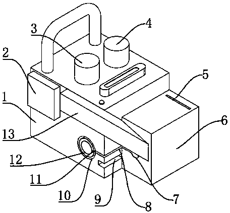
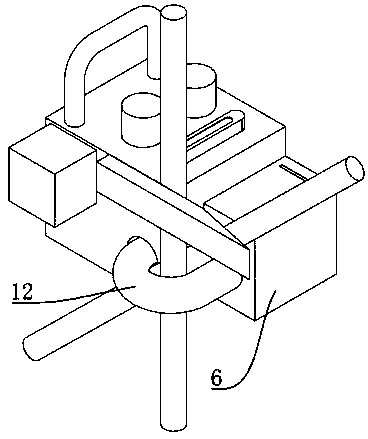
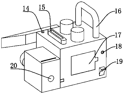
[0017] Such as Figure 1-Figure 3 As shown, a steel bar binding device for beam-column joints includes a fixing base 1, a top block 2 and a binding base 6, a handle 16 is installed on the top of the fixing base 1, and a top block is installed on one side of the handle 16 Button 3, a binding button 4 is installed on one side of the top block button 3, a level 15 is provided on one side of the binding button 4, an indicator light 14 is provided on one side of the level 15, and a Referring to the top block 2, a push rod 13 is installed on one side of the top block 2, a guide hole 10 is arranged below the push rod 13, a guide tube 12 is installed inside the guide hole 10, and a guide tube 12 is arranged on the guide tube 12. Elastic groove 11, the side of described guide hole 10 is provided with contraction groove 8, and described shrinkage groove 8 is provided with chute 9 be...


PUM


Abstract

The invention discloses a device for beam column joint steel bar binding. The device comprises a fixing base, an ejector block and a binding base. A carrying handle is installed on the top of the fixing base. An ejector block button is installed on one side of the carrying handle. A binding button is installed on one side of the ejector block button. A level gauge is arranged on one side of the binding button. An indicator lamp is arranged on one side of the level gauge. The ejector block is installed on the front face of the fixing base. An ejector rod is installed on one side of the ejector block. A guiding hole is formed in the lower face of the ejector rod. A guiding tube is installed inside the guiding hole. An elastic groove is formed in the upper face of the guiding tube. A shrinking groove is formed in one side of the guiding hole. A sliding groove is formed in the lower face of the shrinking groove. A binding base is installed on the sliding groove. The device has the advantages that it is ensured that the binding quality of beam column stirrup and beam column joint beam bottom bar inside a beam column core area is ensured, no bridge side plate needs to be reserved by woodworking, operation is easy, carrying is convenient, the binding process can be efficiently and rapidly completed, and meanwhile the device can be used as the level gauge.

Description

technical field [0001] The invention relates to the design field of steel bar binding devices, in particular to a steel bar binding device for beam-column joints. Background technique [0002] When binding steel bars in building structural engineering, it is difficult to bind steel bars at complex parts such as beam-column joints, which often plagues steel bar binding personnel and formwork support personnel, especially the binding of stirrups at joints. The conventional practice is that when the beam bottom reinforcement is bound at the junction of the middle beam and the column, the carpenter needs to leave the beam side plate to ensure the binding quality of the beam bottom reinforcement. The Chinese patent application number is 201310596338.3. The specific content is: a new labor-saving steel bar binding hook is disclosed, including a binding hook and a driving device for the binding hook. and two springs, one end of the pressure block is fixed on the housing through th...

Claims


Application Information

Patent Timeline
Patent Type & Authority Patents(China)
IPC IPC(8): E04G21/12
CPCE04G21/122
Inventor 张荣华林育峰欧阳宪彬贺龙朝
Owner SHENZHEN SHENGANG CONSTR GRP
Why Eureka
Try Eureka