
A kind of low power consumption eml driving circuit and method

A driving circuit and low power consumption technology, which is applied in the field of optical communication, can solve problems such as difficult application, low efficiency of TEC power circuit, and power consumption reduction of EML driving circuit, so as to reduce power consumption, reduce TEC cooling current, and improve power supply The effect of using efficiency

Active Publication Date: 2018-11-23
XGIGA COMM TECH
View PDF7 Cites 0 Cited by
  • Summary
  • Abstract
  • Description
  • Claims
  • Application Information

AI Technical Summary

Problems solved by technology

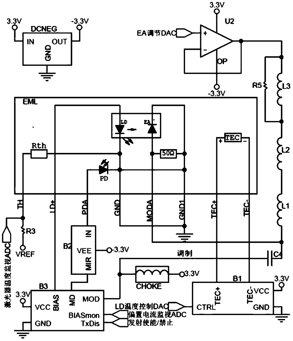
[0006] In the above-mentioned typical EML drive circuit, the TEC power circuit B1 includes two DC / DC converters working simultaneously, and the current flowing through the TEC must completely pass through the two DC / DC converters. effect, making the entire TEC power circuit less efficient
In addition, the laser bias current is generated by the 3.3V power supply, and the absorption current of the EA reverse bias also flows into the -3.3V power supply. These are not conducive to the reduction of power consumption of the EML drive circuit, making it difficult to apply in in the strict module

Method used


Image

  • A kind of low power consumption eml driving circuit and method
  • A kind of low power consumption eml driving circuit and method
  • A kind of low power consumption eml driving circuit and method

Examples


Embodiment Construction

[0034] The present invention will be further described below in conjunction with the accompanying drawings and specific embodiments.

[0035] In order to reduce the power consumption of the EML driving circuit, an embodiment of the present invention provides a low power consumption EML driving circuit and a method.

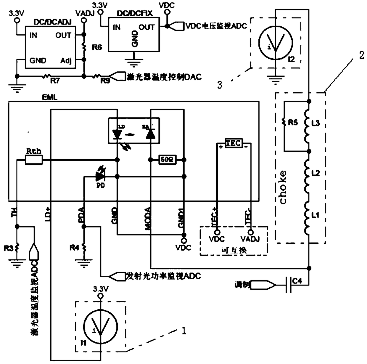
[0036] like figure 1 As shown, a low-power EML driving circuit provided by an embodiment of the present invention includes an electro-absorption modulation laser EML (abbreviated as EML), a DC voltage output terminal VDC of a fixed-output switching power supply DC / DCFIX and the electro-absorption modulation laser The ground signal connection of the laser EML, that is, the VDC voltage is used as the "virtual ground" of the EML component; the laser LD of the EML component is connected in series with the above-mentioned "virtual ground" and the main input power supply (nominal value) through a low-voltage drop bias current circuit 3.3V); the EA of the EML component i...


PUM


Abstract

The invention provides a low-power consumption EML drive circuit, which comprises an eroabsorption modulated laser device EML, wherein a DC voltage output end VDC of a switching power supply DC / DCFIX with a fixed output is connected with a ground signal of the eroabsorption modulated laser device EML, namely a VDC voltage is taken as a 'virtual ground' of an EML assembly; a laser device LD of the EML assembly is connected between the 'virtual ground' and a main input power supply (a nominal value is 3.3V) in series through a low drop-out bias current circuit; an EA of the EML assembly is reversely biased between the 'virtual ground' and a reference ground through a choke and a low drop-out bias voltage adjsuting circuit; and the 'virtual ground' is also directly connected with one end of a refrigerator TEC of the EML assembly. The invention provides a low-power consumption EML drive method. The low-power consumption EML drive circuit and method have the beneficial effect of relatively low power consumption.

Description

technical field [0001] The invention relates to optical communication, in particular to a low power consumption EML driving circuit and method. Background technique [0002] Electroabsorption modulated laser (EML) is an integrated device of electroabsorption modulator (EAM) and DFB laser. It also integrates optical isolator, backlight monitoring PD, TEC cooler, thermistor and other components inside, with high integration, With the characteristics of high speed, long transmission distance and high isolation, it is a general ideal light source for information transmission carriers in high-speed optical fiber transmission networks at home and abroad. [0003] The schematic diagram of an EML component is as follows figure 2 shown. When an appropriate bias current passes through the laser diode LD, part of the light emitted by the laser diode LD enters the backlight monitor PD photodiode and converts it into a current, which is used as a feedback value for APC (Automatic Power...

Claims


Application Information

Patent Timeline
Patent Type & Authority Patents(China)
IPC IPC(8): H01S5/042
CPCH01S5/042
Inventor 吴帅张华安
Owner XGIGA COMM TECH
Learn More