
split slips

A split type, slip technology, applied in the direction of pipe supports, pipes/pipe joints/fittings, mechanical equipment, etc., can solve the problems of poor clamping effect, inaccurate alignment of the first slip and the second slip, etc. , to achieve the effect of improving the clamping stability

Active Publication Date: 2018-07-06
CHENGDU ZHIRONG ZHICHUANG INTPROP MANAGEMENT CO LTD
View PDF10 Cites 0 Cited by
  • Summary
  • Abstract
  • Description
  • Claims
  • Application Information

AI Technical Summary

Problems solved by technology

[0005] The technical problem to be solved by the present invention is to provide a split type slip to overcome the existing slips which easily lead to inaccurate alignment between the first slip and the second slip during the mating process and poor clamping effect The problem

Method used


Image

  • split slips

Examples


Embodiment 1

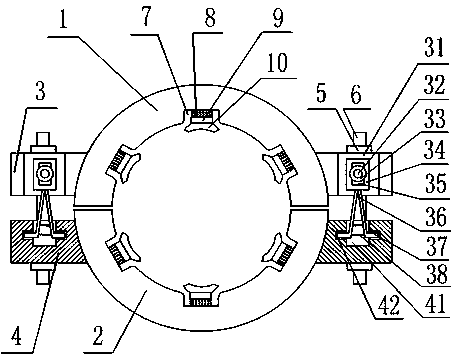
[0032] Such as figure 1 As shown, the split slips include a first slip 1 and a second slip 2, the first slip 1 is provided with a first fixing block 3, the second slip 2 is provided with a second fixing block 4, and the second slip 2 is provided with a second fixing block 4. The first fixed block 3 and the second fixed block 4 are provided with through holes for passing through the screw rod 6, and the first slip 1 and the second slip 2 form fastening slips through the cooperation of the screw rod 6 and the nut 5. The side wall of the first fixed block 3 is provided with a through groove 31, and the bottom of the through groove 31 is provided with a fixed rod 32, and the fixed rod 32 is provided with two fixed pieces 33, and the fixed rod 32 is arranged between the two fixed pieces 33 There is a connecting plate 34, the connecting plate 34 is provided with a perforation 35, the lower end of the connecting plate 34 is hinged with two connecting rods 36, the movable end of the c...

Embodiment 2

[0034] Such as figure 1 As shown, this embodiment is based on Embodiment 1, and the spring 38 is provided with two groups; the perforation 35 is circular or square; the fixing piece 33 is circular or square; The outer wall of 37 is set as a threaded surface; the axial through groove 7 is a rectangular groove; six axial through grooves 7 are uniformly arranged; the axial through groove 7 is connected with the first slip 1 and the second slip 2 arc transition; the clamping end surface of the clamping block 10 is set as an arc surface, and the arc of the arc surface is consistent with the arc of the first slip 1 and the second slip 2; the elastic structure 8 is a spring I .


PUM


Abstract

The invention relates to a split type clamping tile. The split type clamping tile comprises a first clamping tile body and a second clamping tile body. The first clamping tile body is provided with first fixing blocks. The second clamping tile body is provided with second fixing blocks. A through groove is formed in the side wall of each first fixing block. A fixing rod is arranged at the bottom of each through groove. Two fixing pieces are arranged on each fixing rod. A connecting plate is arranged in the position, between the two fixing pieces, of each fixing rod. A punch hole is formed in each connecting plate. Two connecting rods are hinged to the lower end of each connecting plate. A clamping plate is arranged at the free end of each connecting rod. Springs are arranged between every two connecting rods. A groove is formed in each second fixing block. A clamping groove body matched with each clamping plate is formed in the side wall of each groove. The inner wall of the first clamping tile body and the inner wall of the second clamping tile body are each provided with axial through grooves. The bottom of each axial through groove is provided with an elastic structure. A connecting block is connected to the end of each elastic structure. A clamping block is connected to the end of each connecting block. According to the split type clamping tile, the problem that a first clamping tile body and a second clamping tile body are prone to being inaccurate in alignment in the matching process due to an existing clamping tile is solved.

Description

technical field [0001] The invention relates to the field of oil pipeline auxiliary devices, in particular to a split type slip. Background technique [0002] During the transportation of extracted oil, due to the long transportation route, the oil pipelines used for transportation usually use multi-section pipelines for transportation, and multi-section pipelines are connected by multi-section pipelines. In the process of pipeline connection, slips are usually used as the fastening device for pipeline connection. [0003] Slips generally include first slips and second slips forming fastening slips, and the two slips are fixed by bolts. [0004] The existing slips easily lead to inaccurate alignment between the first slip and the second slip during the mating process, and easily lead to poor clamping effect. Contents of the invention [0005] The technical problem to be solved by the present invention is to provide a split type slip to overcome the existing slips which e...

Claims


Application Information

Patent Timeline
IPC IPC(8): F16L3/10
CPCF16L3/1091
Inventor 贺昶明
Owner CHENGDU ZHIRONG ZHICHUANG INTPROP MANAGEMENT CO LTD
Learn More