
Variable inertia variable damping torsional shock absorber

A technology of torsional vibration damper and variable inertia, applied in the direction of rotational vibration suppression, etc., can solve the problems such as the inability to change the vibration damping device and the torsional damping force of the crankshaft, the increased wear of parts, and the torsional vibration of the crankshaft, so as to improve fuel economy, The effect of fast dynamic response and large output damping torque

Active Publication Date: 2017-12-12
CHONGQING UNIV
View PDF5 Cites 0 Cited by
  • Summary
  • Abstract
  • Description
  • Claims
  • Application Information

AI Technical Summary

Problems solved by technology

The crankshaft is subjected to the centrifugal force of the rotating mass, the periodically changing gas inertial force, and the reciprocating inertial force, so that the crankshaft is subjected to bending and torsional loads, which easily causes torsional vibration of the crankshaft, causing cracks and fractures in the shaft system, and aggravated wear of parts. The common method of reducing the torsional vibration of the crankshaft in the prior art is to install a torsional vibration damping device at the front end of the crankshaft. However, the current torsional vibration damping devices are all fixedly installed at the end of the crankshaft, and the torsional damping force between the vibration damping device and the crankshaft cannot be changed. Moreover, it can only have a good vibration-absorbing effect on vibrations of a specific frequency. To offset vibrations of different frequencies, a series of such torsional vibration-damping devices must be added, which has a complex structure and high cost.

Method used


Image

  • Variable inertia variable damping torsional shock absorber
  • Variable inertia variable damping torsional shock absorber
  • Variable inertia variable damping torsional shock absorber

Examples


Embodiment Construction

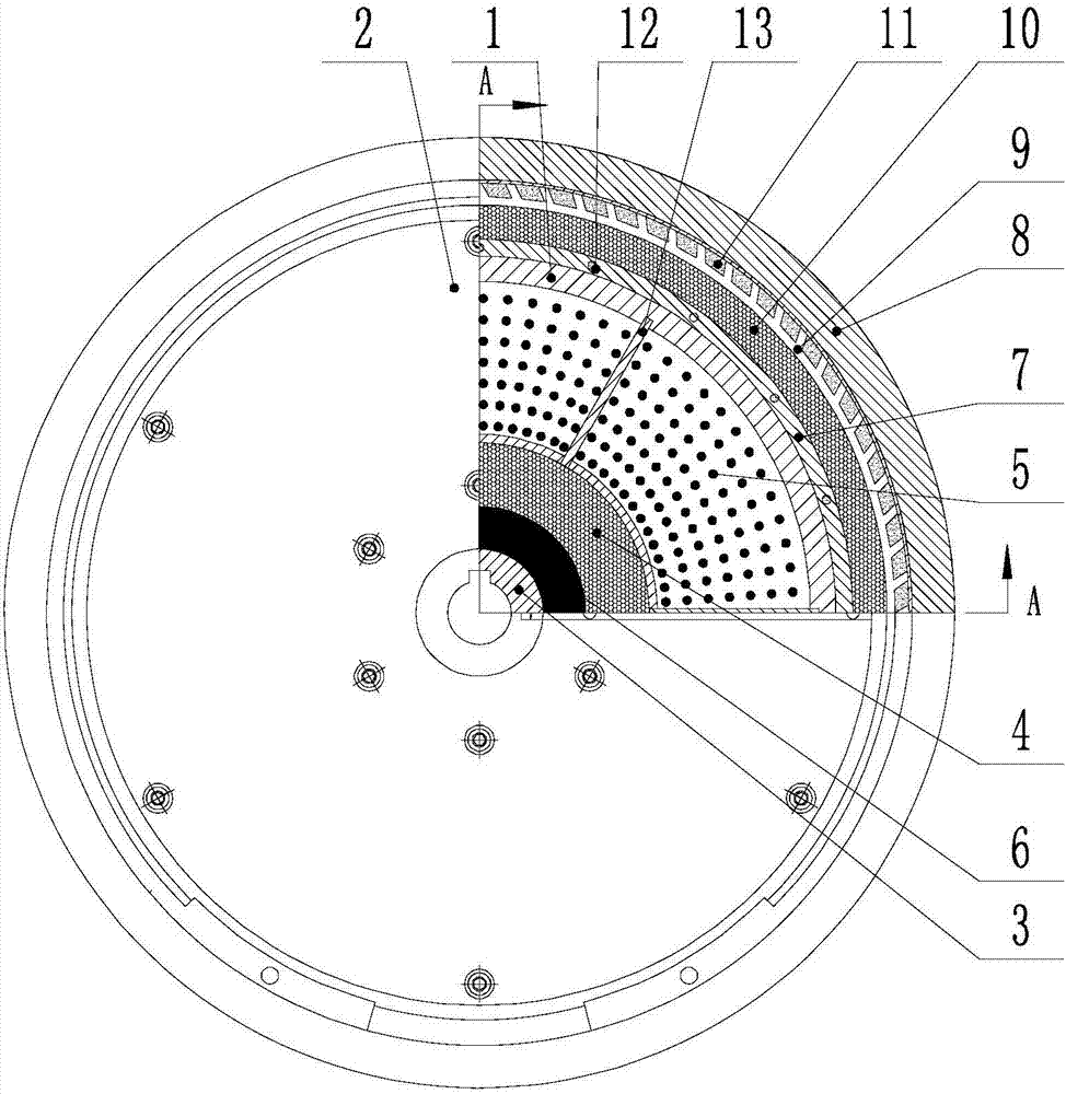
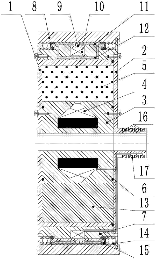
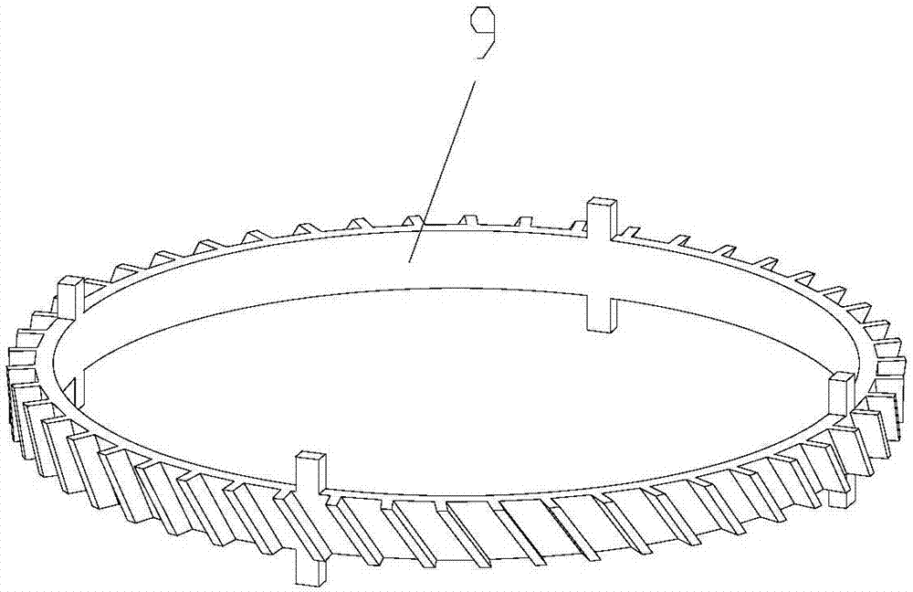
[0013] figure 1 It is a structural schematic diagram of the present invention; figure 2 for figure 1 A-A sectional view of, image 3 It is a schematic diagram of the impeller structure; as shown in the figure: the variable inertia variable damping torsional shock absorber of this embodiment includes a variable inertia component and a variable damping component; the variable inertia component includes a left end plate 1, a right end cover 2, and an inner iron core 3 , internal coil 4, ferrofluid 5 and permanent magnet 6 with variable mass distribution; the left end plate 1 and the right end cover 2 are non-magnetic materials; between the left end plate 1, the right end cover 2 and the inner iron core 3 A closed inner cavity is formed; the ferrofluid 5 is located in the inner cavity; the inner iron core 3 is located on the radial inner side of the inner cavity, and grooves are processed on the inner iron core; the inner coil 4 and the permanent magnet 6 are both Located in t...


PUM


Abstract

The invention discloses a variable-inertia and variable-damping torsion damper. The variable-inertia and variable-damping torsion damper comprises a variable-inertia assembly and a variable-damping assembly; the variable-inertia assembly comprises a left end disk, a right end cover, an inner iron core, a permanent magnet, an inner coil and variable-mass-distribution ferrofluid; and the inner coil and the permanent magnet are combined to generate a magnetic field to change the distribution and the magnitude of a magnetic field at the position of the ferrofluid, and the magnitude of rotating inertia of the variable-inertia assembly is continuously adjusted. The variable-inertia and variable-damping torsion damper can independently serve as a front end torsion damper of an internal combustion engine and can also serve as a secondary flywheel of a dual-mass flywheel to be connected with a clutch; the transmission system damping and the rotating inertia can be adjusted in a self-adaptive manner according to requirements of a control algorithm; and torsion vibration of a transmission system is effectively inhibited. The variable-inertia and variable-damping torsion damper has the beneficial effects that the structure is compact, output damping torque is large, the rotating inertia adjustment range is wide, and the dynamic response is fast; and the fuel oil economy of the internal combustion engine can be improved easily, and the variable-inertia and variable-damping torsion damper can also be applied in a zero-gravity environment of the aerospace and thus has wide application prospects in rotating type mechanical devices.

Description

technical field [0001] The invention relates to a torsional shock absorber, in particular to a torsional shock absorber with variable inertia and variable damping. Background technique [0002] The crankshaft is the most important component in the engine. It bears the force transmitted by the connecting rod and converts it into torque through the crankshaft output and drives other accessories on the engine to work. The crankshaft is subjected to the centrifugal force of the rotating mass, the periodically changing gas inertial force, and the reciprocating inertial force, so that the crankshaft is subjected to bending and torsional loads, which easily causes torsional vibration of the crankshaft, causing cracks and fractures in the shaft system, and aggravated wear of parts. The common method of reducing the torsional vibration of the crankshaft in the prior art is to install a torsional vibration damping device at the front end of the crankshaft. However, the current torsio...

Claims


Application Information

Patent Timeline
Patent Type & Authority Patents(China)
IPC IPC(8): F16F15/16
CPCF16F15/16
Inventor 董小闵于建强陈平根
Owner CHONGQING UNIV
Learn More