Spherical pump cooling mechanism

A technology of cooling mechanism and spherical pump, which is applied in the direction of pumps, pump components, mechanical equipment, etc., can solve problems such as inability to cool friction pairs, high temperature of cylinder block inserts, failure of friction pairs, etc., and achieve low processing costs and high production efficiency. Good processing effect

Active Publication Date: 2017-12-15
深圳市球形动力科技有限公司
View PDF6 Cites 0 Cited by
  • Summary
  • Abstract
  • Description
  • Claims
  • Application Information

AI Technical Summary

Problems solved by technology

During the operation of the spherical pump, since the main moving parts such as the piston, turntable, and center pin are in the flowing liquid, the heat generated during the operation is taken away by the continuously flowing liquid, and the friction between the piston, turntable, and center pin The auxiliary temperature does not rise much, and special cooling is not required; however, the anti-seize power mechanism rotation space formed at the lower part of the cylinder body, the cylinder body seat and the upper end of the main shaft is only partially accumulated by the liquid leaking from the spherical inner cavity, which cannot effectively treat the The friction pair between the main shaft of the spherical pump and the cylinder seat is cooled, which leads to the high temperature of the main shaft bushing as the radial friction pair of the main shaft rotation, especially when using PEEK self-lubricating bearings as the main shaft bushing due to the temperature rise leading to friction At the same time, the anti-seize power mechanism formed by the pin seat on the turntable shaft and the guide rail limit surface on the cylinder seat, because the pin seat continuously contacts and collides with the guide rail limit surface set on the cylinder seat insert Friction, so that the temperature of the cylinder seat insert is too high and fails

Method used


Image

  • Spherical pump cooling mechanism
  • Spherical pump cooling mechanism
  • Spherical pump cooling mechanism

Examples


Embodiment Construction

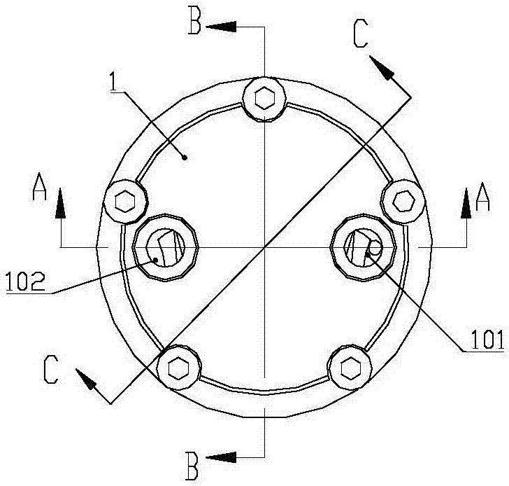
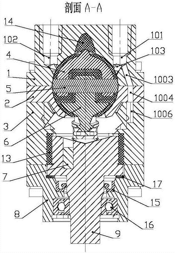
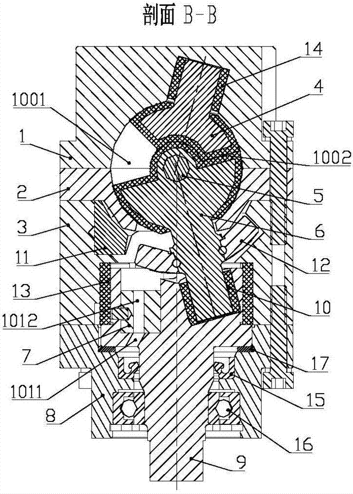
[0033] Such as figure 1 , image 3 , Figure 5 to Figure 8 , Figure 15 , Figure 16 , Figure 19 , Figure 20 As shown, the structure of the spherical compressor is the same as that of the conventional spherical compressor. The spherical pump includes a cylinder head 1, a cylinder body 2, a cylinder seat 3, a piston 4, a center pin 5, a turntable 6, a balance weight 7, a main shaft support 8, and a main shaft 9; The cylinder block 2 has a hemispherical inner spherical surface, a hemispherical lower spherical surface and a flange connected to the cylinder head 1. A through hole adapted to the working process of the turntable shaft is provided in the center of the lower part of the inner spherical surface of the cylinder body 2, that is, the turntable shaft hole; Five screw holes 107 and two pin holes 108 are respectively arranged on the cylinder block 2 and the cylinder head 1, and five corresponding threaded holes 109 and two pin holes 108 are respectively arranged on th...


PUM


Abstract

The invention discloses a cooling mechanism of a ball pump. The cooling mechanism is characterized in that a main liquid inlet hole (101) and a liquid inlet hole (103) which communicate with each other are formed in a cylinder cover (1); the sum of the through flow area of the upper end of a divided flow channel and the through flow area of the liquid inlet hole (103) is not larger than the through flow area of the main liquid inlet hole (101); the lower end of the divided flow channel communicates with a rotation space of an anti-blocking power mechanism; the upper end of a cooling channel (1005) communicates with the rotation space of the anti-blocking power mechanism; the lower end of the cooling channel (1005) communicates with the lower end of a reflux channel; the upper end of the reflux channel is arranged on the cylinder cover (1), and communicates with a liquid inlet channel (104) on an inner spherical surface of the cylinder cover (1); pin boss impeller-shaped surfaces (115) are arranged on two side arms of a pin boss (12) of the anti-blocking power mechanism; and the pin boss impeller-shaped surfaces (115) stir the liquid to generate liquid power. According to the cooling mechanism, the problem that the local temperature is too high during the running process of the ball pump is effectively solved.

Description

technical field [0001] The patent of the present invention relates to a spherical pump cooling mechanism. Background technique [0002] Spherical compressor is a variable displacement mechanism with a new structure newly invented in recent years. Its advantages are no inlet / exhaust valve, less moving parts, small vibration, high mechanical efficiency, reliable sealing, etc. Spherical compressor is used for liquid The pump has different operating characteristics from the existing pump machinery. The spherical pump has the advantages of low operating noise, continuous liquid intake and discharge, and high volumetric efficiency. During the operation of the spherical pump, since the main moving parts such as the piston, turntable, and center pin are in the flowing liquid, the heat generated during the operation is taken away by the continuously flowing liquid, and the friction between the piston, turntable, and center pin The auxiliary temperature does not rise much, and specia...

Claims


Application Information

Patent Timeline
Patent Type & Authority Patents(China)
IPC IPC(8): F04C9/00F04C15/00
CPCF04C9/00F04C15/00F04C15/0096
Inventor 王陆一
Owner 深圳市球形动力科技有限公司
Why Eureka
Try Eureka