
Fodder conveying device

A conveying device and feed technology, which is applied in the direction of conveyors, conveyor objects, transportation and packaging, etc., can solve the problem of no powder material stirring and breaking up, and achieve high stirring force, high breaking efficiency, and increased stirring force Effect

Inactive Publication Date: 2016-07-20
TIANJIN OUSIMEI COMMERCE & TRADE CO LTD
View PDF0 Cites 0 Cited by
  • Summary
  • Abstract
  • Description
  • Claims
  • Application Information

AI Technical Summary

Problems solved by technology

[0003] The problem to be solved by the present invention is that there is no mechanical structure for stirring and breaking up powdery materials in the existing feed conveying device, and a pulverizer is usually needed to realize this function, which wastes time and resources

Method used


Image

  • Fodder conveying device

Examples


Embodiment Construction

[0012] Specific embodiments of the invention will be described in detail below in conjunction with the accompanying drawings.

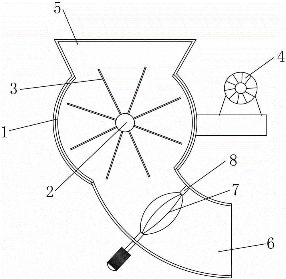
[0013] As shown in the figure, the feed conveying device includes a spherical casing 1, a rotating shaft 2, blades 3 and a driving device 4, the blades 3 are evenly distributed on the circumferential wall of the rotating shaft 2, and the rotating shaft 2 is horizontally mounted on the central axis of the casing 1 , the driving device 4 drives the rotating shaft 2 to rotate in one direction, the upper part of the casing 1 is provided with a feeding port 5, the bottom of the casing 1 is provided with a discharging port 6, and the inner wall of the discharging port 6 is provided with the direction of rotation and the direction of rotation of the rotating shaft Vertical stirring head7.

[0014] The rotation direction of the stirring head 7 is perpendicular to the rotation direction of the rotating shaft 2, and makes a tangential movement with the falling ...


PUM


Abstract

The invention provides a fodder conveying device. The fodder conveying device comprises a spherical machine shell, a rotary shaft, blades and a driving device. The blades are evenly distributed on the circumferential wall of the rotary shaft. The rotary shaft is transversely erected on the central axis of the machine shell. The driving device drives the rotary shaft to rotate unidirectionally. A material inlet is formed in the upper portion of the machine shell. A material outlet is formed in the bottom of the machine shell. A mixing head of which the rotation direction is perpendicular to the rotation direction of the rotary shaft is arranged on the inner wall of the material outlet. The fodder conveying device has the advantages and positive effects that the mixing head can mix and disperse falling powder materials, the moving direction of the mixing head is perpendicular to the moving direction of the rotary shaft, and therefore the mixing head can do tangential movement to the falling materials, the mixing intensity is increased, and the dispersing efficiency is high.

Description

technical field [0001] The invention relates to the field of feed delivery, in particular to a feed delivery device. Background technique [0002] The feed conveyor is often used in the feed production line. The blade rotation in the feed conveyor can drive the material to be transported quantitatively and at a fixed speed to the next link. The feed conveyor is usually used in conjunction with a pulverizer. The pulverizer can pulverize the feed conveyed by the feed conveyor. However, the powdery material itself is easy to disperse, and it only needs to be properly stirred to disperse. If it is crushed with a pulverizer, time and resources are wasted, but there is no machinery for stirring and crushing in the existing feed conveyor. Therefore, there is an urgent need for a feed conveying device with a stirring and crushing structure for breaking up powdery materials, so that there is no need to use a pulverizer. Contents of the invention [0003] The problem to be solved b...

Claims


Application Information

Patent Timeline
Patent Type & Authority Applications(China)
IPC IPC(8): B65G47/00B65G29/02
Inventor 窦宝全
Owner TIANJIN OUSIMEI COMMERCE & TRADE CO LTD
Learn More