Automatic compensation type supporting wheel device and bridge type machining device comprising automatic compensation type supporting wheel device

An automatic compensation and roller technology, applied in metal processing machinery parts, metal processing equipment, stone processing equipment, etc., can solve the problems of increasing material cost and driving cost, increasing the weight of the machine head, losing the stability function, etc., and achieving a compact structure. , The effect of convenient adjustment and maintenance and simple structure

Inactive Publication Date: 2016-07-20
FUJIAN NANAN WANFU MACHINERY CO LTD
View PDF8 Cites 1 Cited by
  • Summary
  • Abstract
  • Description
  • Claims
  • Application Information

AI Technical Summary

Problems solved by technology

But the overall effect is not ideal, one: increasing the weight of the machine head means increasing the material cost and driving cost, and it will increase the expensive scraping cost, because the size of the girder is large, when using the plug iron, the size of the girder must be equal everywhere , which must be shoveled; in addition, the device loses its stabilizing function after wear and tear

Method used


Image

  • Automatic compensation type supporting wheel device and bridge type machining device comprising automatic compensation type supporting wheel device
  • Automatic compensation type supporting wheel device and bridge type machining device comprising automatic compensation type supporting wheel device
  • Automatic compensation type supporting wheel device and bridge type machining device comprising automatic compensation type supporting wheel device

Examples


Embodiment Construction

[0024] The present invention will be described in detail below in conjunction with the accompanying drawings and specific embodiments.

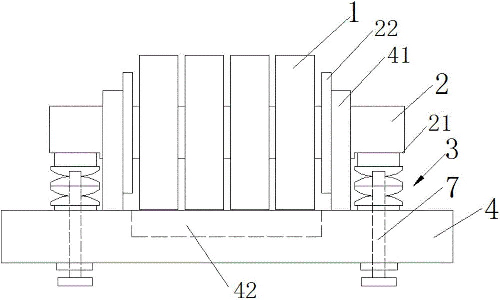
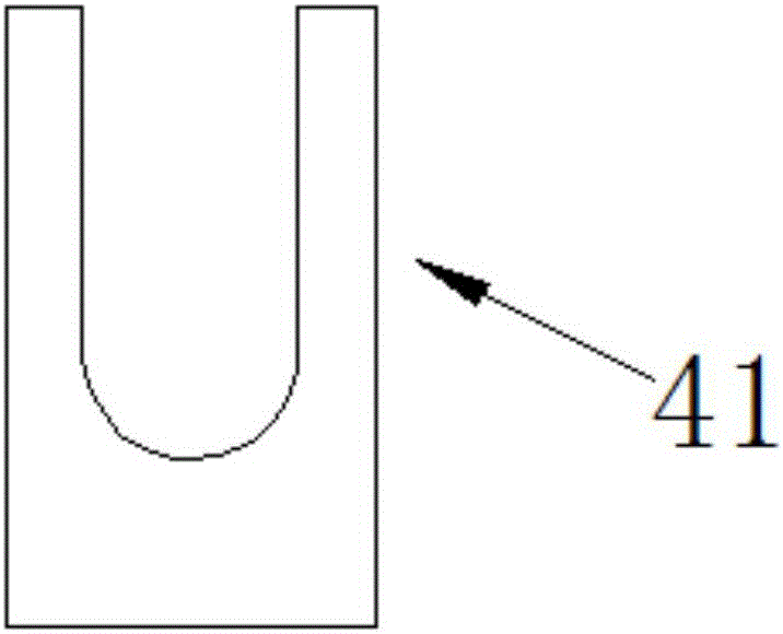
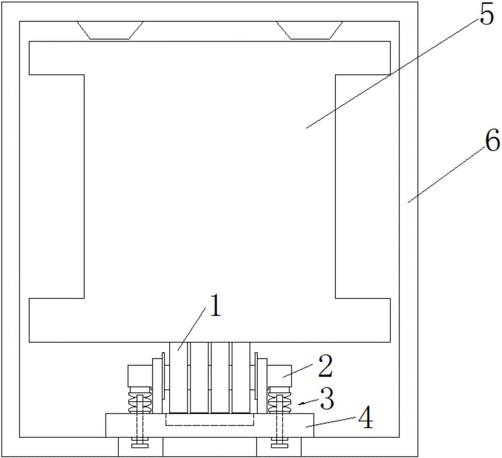
[0025] like figure 1 As shown, an automatic compensating roller device includes a bearing 1 for supporting heavy objects, a bearing support rod 2, an elastic mechanism 3 symmetrically arranged at both ends of the bearing 1, a support 4 and bolts 7; the bearing 1 is set In the middle part of the bearing support rod 2; the bearing support rod 2 is elastically loaded by the bearing support 4 through the elastic mechanism 3; the bolt 7 is threadedly connected with the support support 4 and one end penetrates the elastic mechanism 3; The bearing support rod 2 is horizontally shifted by the limiting lug 41; the bearing 4 is also provided with a bearing relief groove 42 in cooperation with the bearing 1.

[0026] Wherein, a baffle 22 is symmetrically and fixedly arranged on both sides of the bearing 1 on the bearing support rod 2 ;

[0027] Wherei...


PUM


Abstract

The invention relates to an automatic compensation type supporting wheel device. The automatic compensation type supporting wheel device comprises bearings for bearing weights, a bearing supporting rod, elastic mechanisms symmetrically arranged at the two ends of the bearings, a support and bolts. The middle of the bearing supporting rod is sleeved with the bearings. The support elastically bears the bearing supporting rod through the elastic mechanisms. The bolts and the support are connected in a threaded manner, and one end of each bolt penetrates into the corresponding elastic mechanism. The support is provided with limiting supporting lugs for preventing the bearing supporting rod from horizontally shifting; and the support is further provided with bearing avoiding grooves in cooperation with the bearings. The automatic compensation type supporting wheel device and the bridge type machining device comprising the automatic compensation type supporting wheel device can effectively reduce vibration generated in the work process of a machine head, size errors generated in the large beam machining, assembling and using process can be automatically compensated for, long-time stable running of equipment is effectively achieved, and the device is small and ingenious in size, simple in structure, low in cost and long in service life.

Description

technical field [0001] The invention relates to an automatic compensation supporting wheel device and a bridge processing machine including the device, belonging to the field of bridge processing machines. Background technique [0002] Currently widely used in the market, such as gantry planers, gantry milling machines for metal cutting machine tools, and bridge stone cutters and gantry stone cutters in stone equipment. These devices are all bridge-type (gantry) structures, and their machine heads are all hung on the horizontal beams by movable brackets, and move linearly along the beams. Due to the vibration and upward lifting force of the machine head during work, in order to solve this problem, the usual methods are: A: increase the weight of the machine head; Up and down sliding friction to solve the problem of lifting the knife and vibration. But the overall effect is not ideal, one: increasing the weight of the machine head means increasing the material cost and driv...

Claims


Application Information

Patent Timeline
Patent Type & Authority Applications(China)
IPC IPC(8): B23Q11/00B28D7/00
CPCB23Q11/0032B28D7/00
Inventor 李群生
Owner FUJIAN NANAN WANFU MACHINERY CO LTD
Why Eureka
Try Eureka