
Membrane filtration assembly

A membrane filtration and component technology, applied in membrane, membrane technology, semi-permeable membrane separation, etc., can solve the problem of reducing the effective filtration area of ​​the membrane, increasing the outer diameter of the mandrel, and increasing the footprint of a single membrane filtration module, etc. question

Inactive Publication Date: 2016-07-20
CHENGDU MEIFUTE MEMBRANE TECHNOLOGY CO LTD
View PDF9 Cites 18 Cited by
  • Summary
  • Abstract
  • Description
  • Claims
  • Application Information

AI Technical Summary

Problems solved by technology

However, increasing the diameter of the diaphragm will result in a corresponding increase in the footprint of a single membrane filtration module, resulting in a reduction in the number of membrane filtration modules installed and used in limited occasions; if the number of guide vanes and diaphragms is increased , the strength requirement of the mandrel is higher, the diameter of the mandrel needs to be thickened or the mandrel is designed into a double-layer structure according to the conventional method, resulting in a significant increase in the outer diameter of the mandrel, thereby reducing the effective filtration area of ​​the diaphragm, and in addition , increasing the number of deflectors and diaphragms also has higher requirements for the sealing between each diaphragm and the corresponding deflector

Method used


Image

  • Membrane filtration assembly
  • Membrane filtration assembly
  • Membrane filtration assembly

Examples


Embodiment Construction

[0042] The embodiments will be described below in conjunction with the accompanying drawings to illustrate the present invention in detail.

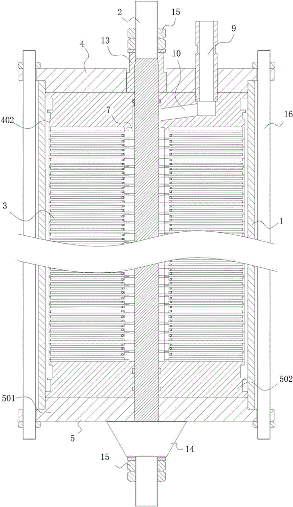
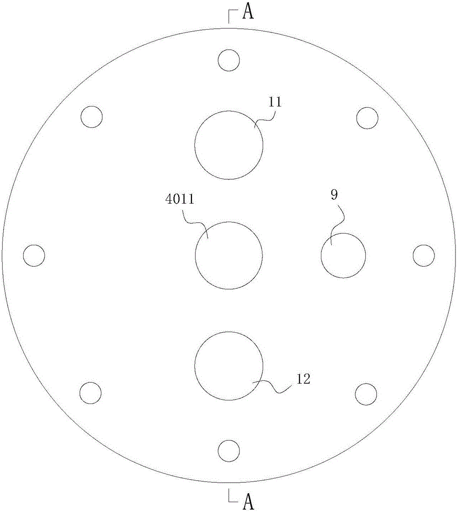
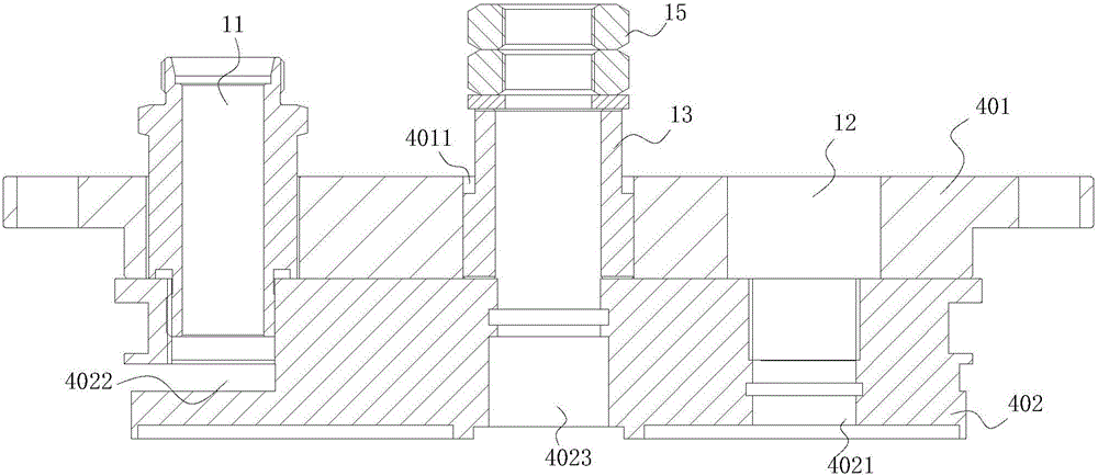
[0043] like Figure 1-8 , the technical solution adopted in the present invention is that the membrane filtration assembly includes a casing 1, a mandrel 2, a filter structure 3, an upper cover assembly 4, and a lower cover assembly 5, wherein the upper cover assembly 4 is arranged on the upper end of the mandrel 2, and the lower The cover assembly 5 is arranged at the lower end of the mandrel 2, the filter structure 3 is sleeved on the mandrel 2 and axially pressed between the upper cover assembly 4 and the lower cover assembly 5 through the fastening structure, and the housing 1 is arranged on the filter structure 3 The outside of the upper cover assembly 4 and the lower cover assembly 5 are respectively connected; the filter structure 3 includes several deflector plates 301 and diaphragms 302 that are sequentially sleeved on the mandr...


PUM


Abstract

The invention relates to a membrane filtration assembly, in particular to a nanofiltration or reverse osmosis membrance filtering assembly in the water treatment field. The invention discloses the membrane filtration assembly high in filtering efficiency in order to overcome the defect that an existing membrane filtration assembly is low in filtering efficiency. The assembly comprises a shell, a mandrel, a filtering structure, an upper cover assembly and a lower cover assembly. The upper cover assembly is arranged at the upper end of the mandrel, the lower cover assembly is disposed at the lower end of the mandrel, the mandrel is sleeved with the filtering structure, the filtering structure is axially pressed between the upper cover assembly and the lower cover assembly through a fastening structure, and the shell is arranged outside the filtering structure and connected with the upper cover assembly and the lower cover assembly. The filtering stricture comprises a plurality of flow guide discs and membranes, the flow guide discs and the membranes are sequentially sleeved with the mandrel in the axial direction of the mandrel. Each membrane is installed between every two adjacent flow guide discs. By selecting and combining some key parameters of the membranes through the membrane filtering assembly, filtering efficiency of the membrane filtering assembly can be higher, and the filtering rejection rate is unexpectedly good.

Description

technical field [0001] The invention relates to a membrane filter assembly, in particular to a nanofiltration or reverse osmosis membrane filter assembly in the field of water treatment. Background technique [0002] The applicant of the present application has developed a membrane filter assembly mainly used for sewage nanofiltration or reverse osmosis treatment. This membrane filter assembly includes a shell, a mandrel, a filter structure, an upper cover assembly, and a lower cover assembly. The upper cover assembly is arranged on The upper end of the mandrel, the lower cover assembly is arranged on the lower end of the mandrel, the filter structure is sleeved on the mandrel and axially pressed between the upper cover assembly and the lower cover assembly through the fastening structure, and the outer shell is arranged outside the filter structure And respectively connect the upper cover assembly and the lower cover assembly. Wherein, the filter structure includes hundred...

Claims


Application Information

Patent Timeline
IPC IPC(8): B01D63/08B01D61/08B01D61/00C02F1/44
CPCB01D63/082B01D61/025B01D61/027B01D61/08B01D2313/025B01D2313/04B01D2313/21C02F1/441C02F1/442
Inventor 宋岱峰韩亮
Owner CHENGDU MEIFUTE MEMBRANE TECHNOLOGY CO LTD
Learn More