


Quick Research
Generate reliable direction feasibility study reports for your R&D in just a few steps.

Technical Q&A
Discover and master advanced knowledge NOW. Basics, ideas, possibilities, all at once.

Find Solutions
As an expert in R&D theories, this can generate solutions to your technical problems instantly.

Evaluate Feasibility
Analyze your overall solution with one click, know your potential R&D risks in advance.

Monitor Landscape
Get weekly tech updates, stay abreast of the latest tech innovations and key insights.
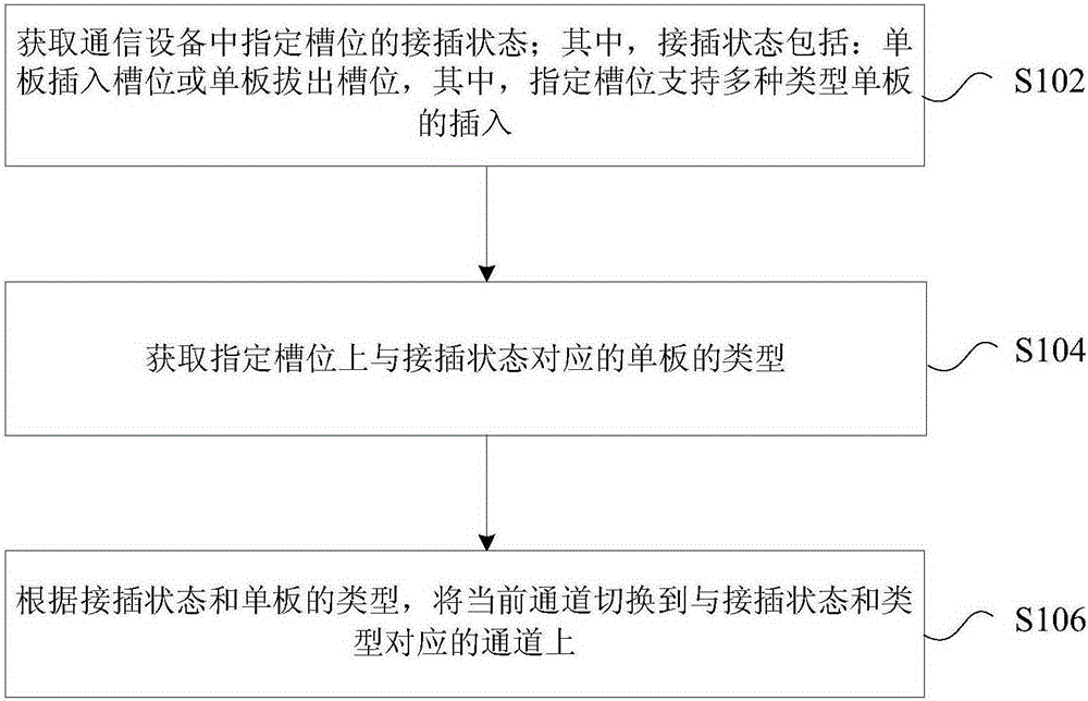
Channel switching method and apparatus, backboard, and communication device
A technology for channel switching and communication equipment, applied in the field of backplane and communication equipment, channel switching method and device, can solve the problem of inflexible subrack configuration, and achieve the effects of solving inflexible configuration, improving utilization, and enhancing flexibility
- Summary
- Abstract
- Description
- Claims
- Application Information
AI Technical Summary
Problems solved by technology
Method used
Image

Examples
Embodiment 1
[0100] Mixed half-height boards and full-height boards are inserted in the same slot, and the Ethernet GE network port is automatically switched.
[0101] Figure 10 It is a schematic diagram of slot addresses 10, 17, and 30 of the subrack in Embodiment 1 of the present invention compatible with full-height boards and half-height boards. A, B, and X (equivalent to Figure 5The connectors of the illustrated embodiment) respectively represent the common signal socket of the half-height board and the common signal socket of the full-height board. In the following, the network port is used as the representative of the high-speed port for description, such as Figure 10 as shown,
[0102] When inserting two half-height boards, the slot addresses are 10 and 17 respectively. If inserting a full-height board, the slot address is 30. Since A and X on the left are not compatible, 2 network ports are required - 2 half-height boards are compatible with 1 full-height board and a total ...
Embodiment 2
[0109] Half-height boards and full-height boards are mixed in the same slot, and PCIE channels are switched adaptively.
[0110] Figure 11 It is a schematic diagram of slot addresses 10, 17, and 30 of the subrack in Embodiment 2 of the present invention compatible with full-height boards and half-height boards. A, B, and X (equivalent to Figure 5 The connectors of the illustrated embodiment) respectively represent the common signal socket of the half-height board and the common signal socket of the full-height board. The following uses PCIE as the representative of the high-speed port for description, such as Figure 11 Shown:
[0111] When inserting two half-height boards, the slot addresses are 10 and 17 respectively. If inserting a full-height board, the slot address is 30. In order to support PCIE multi-channel and multi-mode mixed insertion self-adaptation on the backplane, a PCIE master or PCIE switch chip is required to provide a 4-channel access connection to the...
Embodiment 3
[0117] Half-height boards, full-height boards, and double-layer full-height boards are mixed in the same slot, and PCIE channels are adaptively switched.
[0118] Figure 12 It is a schematic diagram of slot addresses 9, 10, 17, 18, 30, 31, and 60 of the subrack in Embodiment 3 of the present invention compatible with single-layer full-height boards, double-layer full-height boards, and half-height boards. A, B, C, D, S, L and X represent the common signal sockets of half-height boards, the common signal sockets of single-layer full-height boards and the common signal sockets of double-layer full-height boards, respectively. The following uses PCIE as the representative of the high-speed port for description, such as Figure 12 Shown:
[0119] When inserting four half-height boards, the slot addresses are 9, 10, 17, and 18 respectively. If inserting two single-layer full-height boards, the slot addresses are 30 and 31. If inserting double-layer full-height boards, the slot a...
PUM
 Abstract
Description
Claims
Application Information
 - R&D Engineer
- R&D Manager
- IP Professional
- Industry Leading Data Capabilities
- Powerful AI technology
- Patent DNA Extraction
Browse by: Latest US Patents, China's latest patents, Technical Efficacy Thesaurus, Application Domain, Technology Topic, Popular Technical Reports.
© 2024 PatSnap. All rights reserved.Legal|Privacy policy|Modern Slavery Act Transparency Statement|Sitemap|About US| Contact US: help@patsnap.com